Cirkit Designer
Your all-in-one circuit design IDE
Home /
Component Documentation
How to Use XLINE 16 Line Follower: Examples, Pinouts, and Specs
Introduction
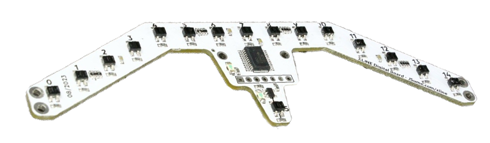
The XLINE 16 Line Follower is a sensor module designed by ROBOLİG(KOKBORU) for detecting and following lines on a surface. This component is commonly used in automated guided vehicles (AGVs) and robots for navigation purposes. By utilizing an array of sensors, the XLINE 16 can accurately detect the presence and position of lines, enabling precise control and movement along predefined paths.
Explore Projects Built with XLINE 16 Line Follower
Arduino UNO Line Follower Robot with IR Sensors and L298N Motor Driver
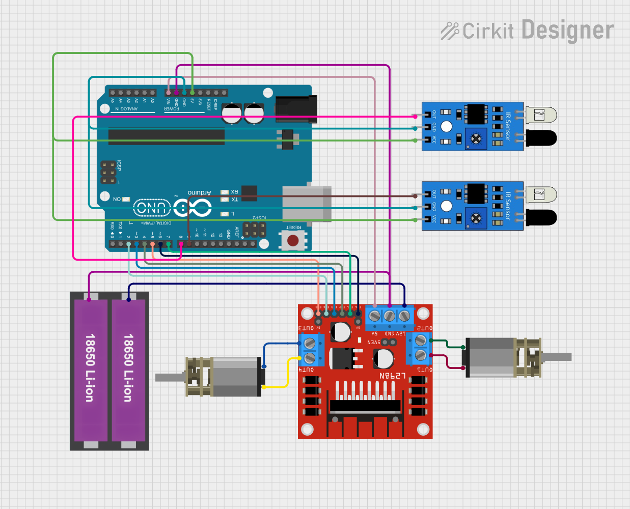
This circuit is a line follower robot controlled by an Arduino UNO. It uses two IR sensors to detect the line and an L298N motor driver to control two DC motors, enabling the robot to follow the line by adjusting its direction based on sensor inputs.
Arduino Nano Line Follower Robot with PID Control and Sensor Array
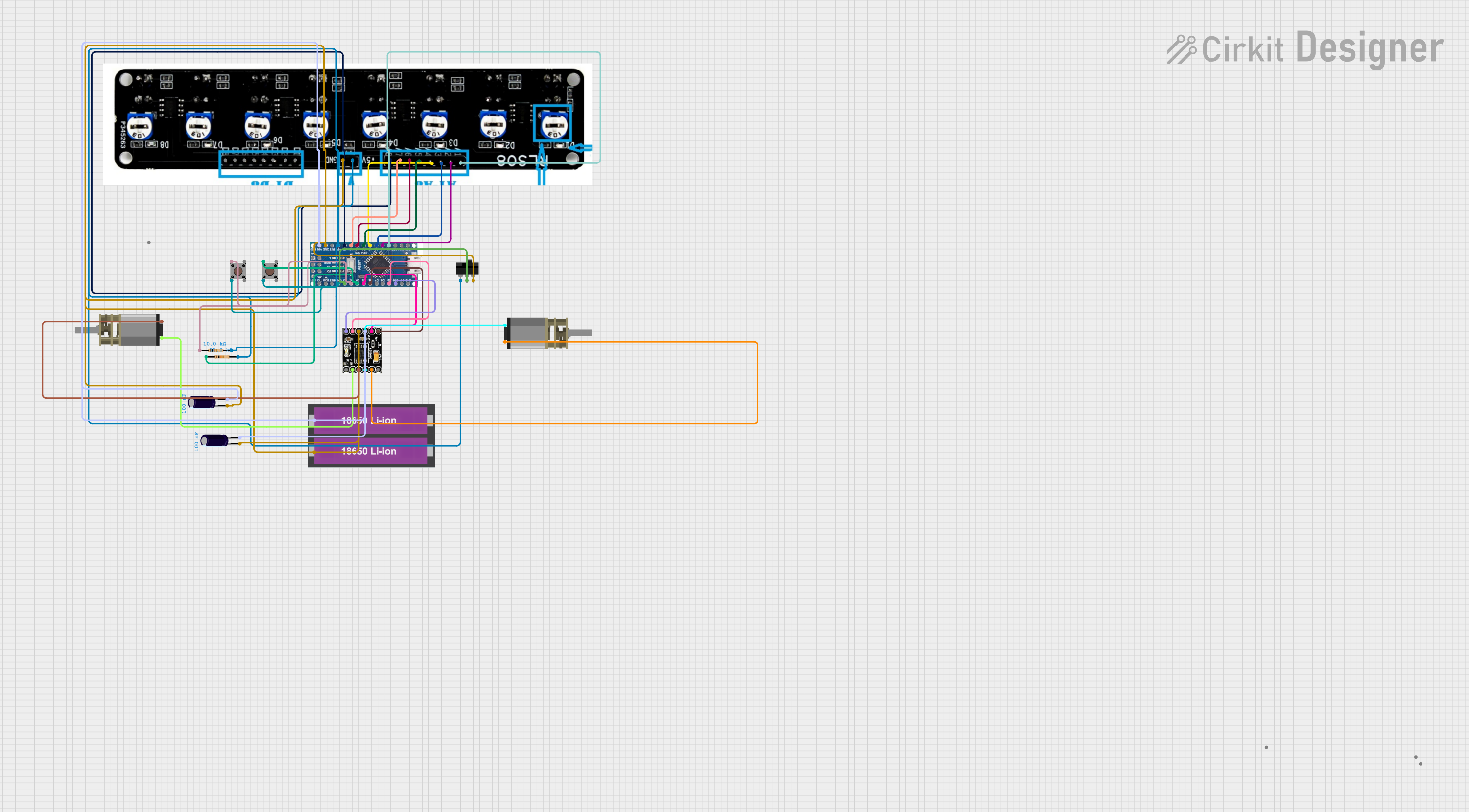
This circuit is a line follower robot controlled by an Arduino Nano, utilizing a PID control algorithm for stability. It includes a sensor array to detect the line, two DC motors driven by a DRV8833 motor driver, and user inputs via a toggle switch and pushbuttons for calibration and operation. The robot follows a black line on a white surface, making precise turns at curves or edges.
Arduino UNO Line Following Robot with L298N Motor Driver and Battery Power
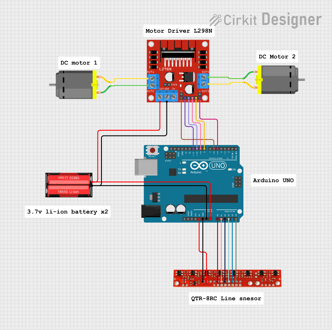
This circuit is a line-following robot controlled by an Arduino UNO. It uses a line sensor array to detect the path and an L298N motor driver to control two DC motors, enabling the robot to follow a line autonomously.
Arduino UNO Line Following Robot with L298N Motor Driver and KY-033 Sensors
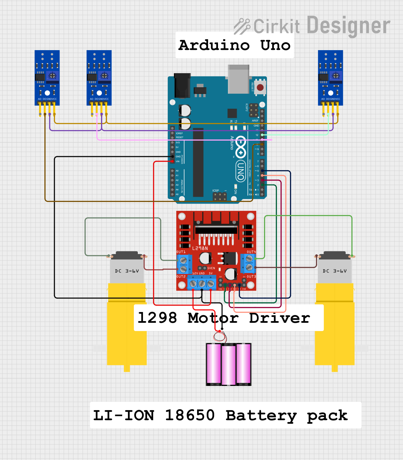
This circuit is a line-following robot controlled by an Arduino UNO. It uses three KY-033 line tracking sensors to detect the path and an L298N motor driver to control two DC motors, powered by a 12V battery. The Arduino processes sensor inputs to adjust motor speeds and directions, enabling the robot to follow a line.
Explore Projects Built with XLINE 16 Line Follower
Arduino UNO Line Follower Robot with IR Sensors and L298N Motor Driver
This circuit is a line follower robot controlled by an Arduino UNO. It uses two IR sensors to detect the line and an L298N motor driver to control two DC motors, enabling the robot to follow the line by adjusting its direction based on sensor inputs.
Arduino Nano Line Follower Robot with PID Control and Sensor Array
This circuit is a line follower robot controlled by an Arduino Nano, utilizing a PID control algorithm for stability. It includes a sensor array to detect the line, two DC motors driven by a DRV8833 motor driver, and user inputs via a toggle switch and pushbuttons for calibration and operation. The robot follows a black line on a white surface, making precise turns at curves or edges.
Arduino UNO Line Following Robot with L298N Motor Driver and Battery Power
This circuit is a line-following robot controlled by an Arduino UNO. It uses a line sensor array to detect the path and an L298N motor driver to control two DC motors, enabling the robot to follow a line autonomously.
Arduino UNO Line Following Robot with L298N Motor Driver and KY-033 Sensors
This circuit is a line-following robot controlled by an Arduino UNO. It uses three KY-033 line tracking sensors to detect the path and an L298N motor driver to control two DC motors, powered by a 12V battery. The Arduino processes sensor inputs to adjust motor speeds and directions, enabling the robot to follow a line.
Technical Specifications
Key Technical Details
| Specification | Value |
|---|---|
| Manufacturer | ROBOLİG(KOKBORU) |
| Part ID | kokboru0042 Model |
| Operating Voltage | 3.3V - 5V |
| Operating Current | 100mA (max) |
| Number of Sensors | 16 |
| Output Type | Digital |
| Communication | I2C |
| Dimensions | 100mm x 20mm x 10mm |
| Weight | 15g |
Pin Configuration and Descriptions
| Pin Number | Pin Name | Description |
|---|---|---|
| 1 | VCC | Power supply (3.3V - 5V) |
| 2 | GND | Ground |
| 3 | SDA | I2C Data Line |
| 4 | SCL | I2C Clock Line |
| 5-20 | D0-D15 | Digital outputs from each sensor (D0 for sensor 0, D1 for sensor 1, etc.) |
Usage Instructions
How to Use the Component in a Circuit
- Power Supply: Connect the VCC pin to a 3.3V or 5V power supply and the GND pin to the ground of your circuit.
- I2C Communication: Connect the SDA and SCL pins to the corresponding I2C pins on your microcontroller (e.g., Arduino UNO).
- Digital Outputs: The digital output pins (D0-D15) can be connected to digital input pins on your microcontroller to read the state of each sensor.
Important Considerations and Best Practices
- Power Supply: Ensure that the power supply voltage is within the specified range (3.3V - 5V) to avoid damaging the sensor module.
- I2C Pull-up Resistors: If your microcontroller does not have internal pull-up resistors for the I2C lines, you may need to add external pull-up resistors (typically 4.7kΩ) between the SDA/SCL lines and VCC.
- Sensor Calibration: Depending on the surface and lighting conditions, you may need to calibrate the sensors to achieve optimal performance. This can be done by adjusting the threshold values in your code.
Example Code for Arduino UNO
#include <Wire.h>

#define SENSOR_ADDRESS 0x3C // I2C address of the XLINE 16 Line Follower

void setup() {
  Serial.begin(9600); // Initialize serial communication
  Wire.begin();       // Initialize I2C communication
}

void loop() {
  Wire.beginTransmission(SENSOR_ADDRESS);
  Wire.write(0x00); // Request data from the sensor
  Wire.endTransmission();

  Wire.requestFrom(SENSOR_ADDRESS, 16); // Request 16 bytes of data

  while (Wire.available()) {
    for (int i = 0; i < 16; i++) {
      int sensorValue = Wire.read(); // Read each sensor value
      Serial.print("Sensor ");
      Serial.print(i);
      Serial.print(": ");
      Serial.println(sensorValue);
    }
  }

  delay(100); // Delay for readability
}
Troubleshooting and FAQs
Common Issues Users Might Face
- No Sensor Data: If you are not receiving any data from the sensor, check the I2C connections and ensure that the sensor is powered correctly.
- Inconsistent Readings: If the sensor readings are inconsistent, try calibrating the sensors and ensure that the surface is clean and well-lit.
- I2C Communication Errors: If you encounter I2C communication errors, check the pull-up resistors on the SDA and SCL lines and ensure that the I2C address is correct.
Solutions and Tips for Troubleshooting
- Check Connections: Ensure that all connections are secure and that there are no loose wires.
- Verify Power Supply: Make sure that the power supply voltage is within the specified range (3.3V - 5V).
- Calibrate Sensors: Adjust the threshold values in your code to calibrate the sensors for different surfaces and lighting conditions.
- Use Pull-up Resistors: If necessary, add external pull-up resistors (typically 4.7kΩ) between the SDA/SCL lines and VCC to ensure proper I2C communication.
By following this documentation, you should be able to effectively integrate and utilize the XLINE 16 Line Follower in your robotics projects. If you encounter any issues or have further questions, please refer to the troubleshooting section or contact the manufacturer for support.