
How to Use 50 V / 10A DC-DC power filter module: Examples, Pinouts, and Specs
 Design with 50 V / 10A DC-DC power filter module in Cirkit Designer
Introduction
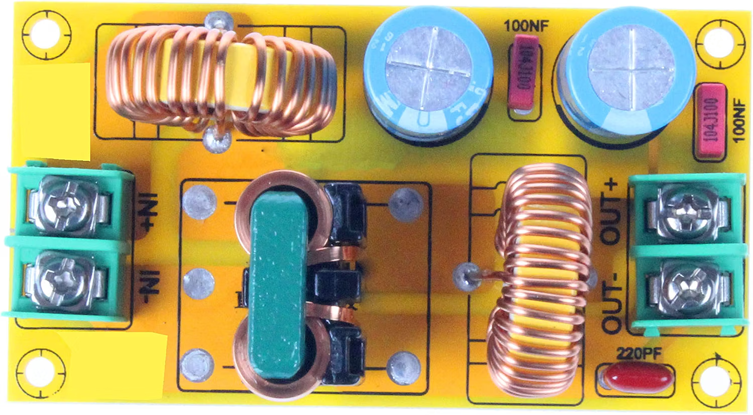
The NOYITO 50 V / 10A DC-DC Power Filter Module is a versatile electronic component designed to stabilize and filter DC power supplies. It effectively reduces noise, ripple, and other electrical disturbances, ensuring a clean and stable output voltage. This module is capable of handling input voltages up to 50 V and currents up to 10 A, making it suitable for high-power applications.
Explore Projects Built with 50 V / 10A DC-DC power filter module
 Open Project in Cirkit Designer
 Open Project in Cirkit Designer
 Open Project in Cirkit Designer
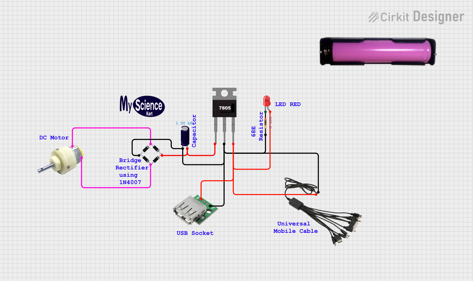 Open Project in Cirkit Designer
Explore Projects Built with 50 V / 10A DC-DC power filter module
Open Project in Cirkit DesignerOpen Project in Cirkit DesignerOpen Project in Cirkit DesignerOpen Project in Cirkit DesignerCommon Applications and Use Cases
- Power supply noise filtering for sensitive electronic devices
- Voltage stabilization in DC circuits
- Applications in automotive electronics, industrial equipment, and robotics
- Protection of microcontrollers, sensors, and communication modules from power fluctuations
Technical Specifications
Below are the key technical details of the NOYITO 50 V / 10A DC-DC Power Filter Module:
| Parameter | Specification |
|---|---|
| Input Voltage Range | 0 V to 50 V DC |
| Maximum Current | 10 A |
| Output Voltage Range | Same as input (pass-through design) |
| Ripple Suppression | High efficiency |
| Operating Temperature | -40°C to +85°C |
| Dimensions | 60 mm x 25 mm x 20 mm |
| Weight | ~30 g |
Pin Configuration and Descriptions
The module has four connection points, as described below:
| Pin Name | Description |
|---|---|
| VIN+ | Positive input voltage terminal |
| VIN- | Negative input voltage terminal (ground) |
| VOUT+ | Positive output voltage terminal |
| VOUT- | Negative output voltage terminal (ground) |
Usage Instructions
How to Use the Component in a Circuit
- Connect the Input Terminals:
- Connect the positive terminal of your DC power source to the
VIN+pin. - Connect the negative terminal of your DC power source to the
VIN-pin.
- Connect the positive terminal of your DC power source to the
- Connect the Output Terminals:
- Connect the
VOUT+pin to the positive terminal of your load. - Connect the
VOUT-pin to the negative terminal of your load.
- Connect the
- Verify Connections:
- Double-check all connections to ensure proper polarity and secure wiring.
- Power On:
- Turn on the DC power source. The module will filter the input voltage and provide a clean, stable output to the load.
Important Considerations and Best Practices
- Input Voltage: Ensure the input voltage does not exceed 50 V DC to avoid damaging the module.
- Current Handling: Do not exceed the 10 A current limit to prevent overheating or failure.
- Heat Dissipation: For high-current applications, consider adding a heatsink or active cooling to maintain safe operating temperatures.
- Polarity: Always observe correct polarity when connecting the module to avoid damage.
- Mounting: Secure the module in your circuit to prevent vibrations or loose connections.
Example: Using with an Arduino UNO
The module can be used to provide a clean power supply to an Arduino UNO. Below is an example of how to connect the module:
- Connect a 12 V DC power source to the
VIN+andVIN-pins of the module. - Connect the
VOUT+andVOUT-pins to the Arduino'sVINandGNDpins, respectively. - Use the following Arduino code to test the setup:
// Simple Arduino code to blink an LED
// Ensure the power filter module is providing clean power to the Arduino

const int ledPin = 13; // Built-in LED pin on Arduino UNO

void setup() {
  pinMode(ledPin, OUTPUT); // Set LED pin as output
}

void loop() {
  digitalWrite(ledPin, HIGH); // Turn the LED on
  delay(1000);               // Wait for 1 second
  digitalWrite(ledPin, LOW);  // Turn the LED off
  delay(1000);               // Wait for 1 second
}
Troubleshooting and FAQs
Common Issues Users Might Face
No Output Voltage:
- Cause: Incorrect wiring or reversed polarity.
- Solution: Verify all connections and ensure correct polarity.
Excessive Heat:
- Cause: Current exceeding 10 A or insufficient cooling.
- Solution: Reduce the load current or add a heatsink/active cooling.
Ripple Not Reduced:
- Cause: Input voltage contains excessive noise beyond the module's filtering capacity.
- Solution: Use additional filtering components (e.g., capacitors) in conjunction with the module.
Module Not Working:
- Cause: Input voltage exceeds 50 V or module is damaged.
- Solution: Replace the module and ensure input voltage is within the specified range.
Solutions and Tips for Troubleshooting
- Use a multimeter to measure input and output voltages to confirm proper operation.
- Inspect the module for physical damage, such as burnt components or broken solder joints.
- Ensure the power source is stable and capable of supplying the required current.
By following this documentation, users can effectively integrate the NOYITO 50 V / 10A DC-DC Power Filter Module into their projects and ensure reliable performance.