How to Use Load Cell Amplifier: Examples, Pinouts, and Specs
Introduction
A Load Cell Amplifier is an electronic device designed to amplify the small electrical signals generated by a load cell, which measures weight or force. Load cells typically produce millivolt-level signals that are too weak to be directly processed by most microcontrollers or data acquisition systems. The amplifier boosts these signals to a more usable voltage range, enabling accurate measurement and processing.
Explore Projects Built with Load Cell Amplifier


Explore Projects Built with Load Cell Amplifier
Common Applications and Use Cases
- Digital weighing scales
- Industrial force measurement systems
- Robotics and automation for weight sensing
- Laboratory testing equipment
- IoT-based weight monitoring systems
Technical Specifications
Below are the typical technical specifications for a Load Cell Amplifier. Note that actual values may vary depending on the specific model.
| Parameter | Specification |
|---|---|
| Input Voltage Range | 3.3V to 5V DC |
| Output Voltage Range | 0V to 5V (or proportional to input signal) |
| Gain | Adjustable (e.g., 64x, 128x) |
| Input Signal Range | ±20mV (typical for load cells) |
| Operating Temperature | -40°C to 85°C |
| Communication Interface | Analog output or digital (e.g., I2C/SPI) |
Pin Configuration and Descriptions
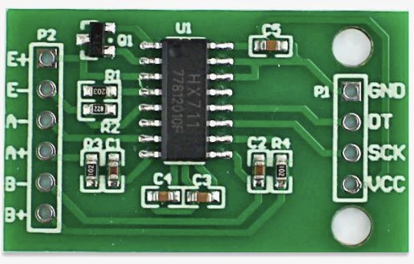
The following table describes the pinout for a common Load Cell Amplifier module, such as the HX711:
| Pin Name | Description |
|---|---|
| VCC | Power supply input (3.3V or 5V DC) |
| GND | Ground connection |
| DT (Data) | Digital data output (used for communication with microcontrollers) |
| SCK (Clock) | Serial clock input (used for synchronizing data communication) |
| E+ | Positive excitation voltage for the load cell |
| E- | Negative excitation voltage for the load cell |
| A+ | Positive signal input from the load cell |
| A- | Negative signal input from the load cell |
Usage Instructions
How to Use the Load Cell Amplifier in a Circuit
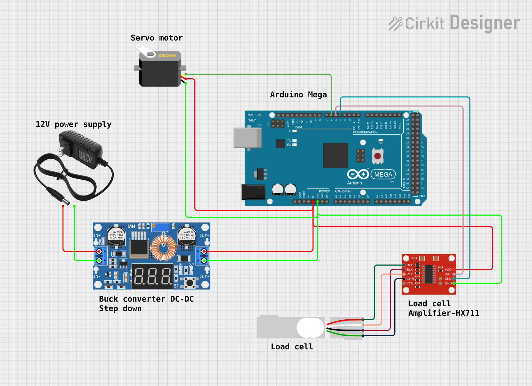
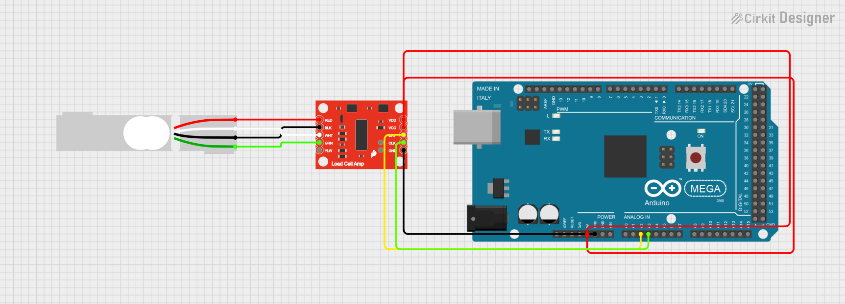
- Connect the Load Cell:
- Attach the load cell wires to the amplifier's input pins (A+, A-, E+, E-). Ensure proper polarity.
- Power the Amplifier:
- Connect the VCC pin to a 3.3V or 5V power source and the GND pin to ground.
- Interface with a Microcontroller:
- Connect the DT and SCK pins to the corresponding digital pins on your microcontroller.
- Calibrate the System:
- Perform a calibration routine to map the amplifier's output to actual weight or force values.
Important Considerations and Best Practices
- Shielded Cables: Use shielded cables for the load cell connections to minimize noise.
- Stable Power Supply: Ensure a stable and noise-free power supply for accurate measurements.
- Temperature Effects: Be aware that temperature changes can affect load cell readings; consider temperature compensation if needed.
- Gain Adjustment: Adjust the amplifier's gain setting to match the sensitivity of your load cell.
Example: Using the HX711 Load Cell Amplifier with Arduino UNO
Below is an example Arduino sketch for interfacing the HX711 Load Cell Amplifier with an Arduino UNO:
#include "HX711.h" // Include the HX711 library

// Define the pins connected to the HX711 module
#define DT_PIN 3  // Data pin connected to Arduino digital pin 3
#define SCK_PIN 2 // Clock pin connected to Arduino digital pin 2

HX711 scale; // Create an instance of the HX711 class

void setup() {
  Serial.begin(9600); // Initialize serial communication at 9600 baud
  scale.begin(DT_PIN, SCK_PIN); // Initialize the HX711 with the defined pins

  Serial.println("Calibrating... Place a known weight on the scale.");
  delay(5000); // Wait for 5 seconds to allow calibration
  scale.set_scale(); // Set the scale to default calibration factor
  scale.tare(); // Reset the scale to zero
  Serial.println("Calibration complete.");
}

void loop() {
  // Read the weight from the load cell
  float weight = scale.get_units(10); // Average 10 readings for stability
  Serial.print("Weight: ");
  Serial.print(weight);
  Serial.println(" kg"); // Display the weight in kilograms

  delay(1000); // Wait 1 second before the next reading
}
Notes:
- Install the HX711 library in the Arduino IDE before uploading the code.
- Replace
scale.set_scale()with a calibration factor specific to your load cell for accurate readings.
Troubleshooting and FAQs
Common Issues and Solutions
No Output or Incorrect Readings:
- Verify all connections, especially the load cell wiring.
- Ensure the power supply voltage matches the amplifier's requirements.
- Check for loose or damaged wires.
Fluctuating or Noisy Readings:
- Use shielded cables to reduce electromagnetic interference.
- Place the load cell on a stable surface to avoid vibrations.
- Add a capacitor across the power supply pins to filter noise.
Calibration Problems:
- Ensure the load cell is unloaded during the tare process.
- Use a precise known weight for calibration.
FAQs
Q: Can I use a 3.3V microcontroller with the Load Cell Amplifier?
A: Yes, most amplifiers like the HX711 support both 3.3V and 5V logic levels.
Q: How do I determine the calibration factor for my load cell?
A: Place a known weight on the load cell, read the raw output, and calculate the factor by dividing the known weight by the raw value.
Q: Can I connect multiple load cells to a single amplifier?
A: No, most amplifiers are designed for a single load cell. Use a summing junction or a multi-channel amplifier for multiple load cells.
Q: What is the maximum weight my load cell can measure?
A: This depends on the load cell's rated capacity. Check the load cell's datasheet for details.