How to Use USB Cable: Examples, Pinouts, and Specs
Introduction
A USB (Universal Serial Bus) cable is a widely used electronic component designed for connecting devices to facilitate data transfer and power delivery. It typically features a USB connector on one or both ends and supports various USB standards, such as USB 2.0, USB 3.0, and USB-C. USB cables are essential in modern electronics, enabling communication between computers, smartphones, peripherals, and other devices.
Explore Projects Built with USB Cable


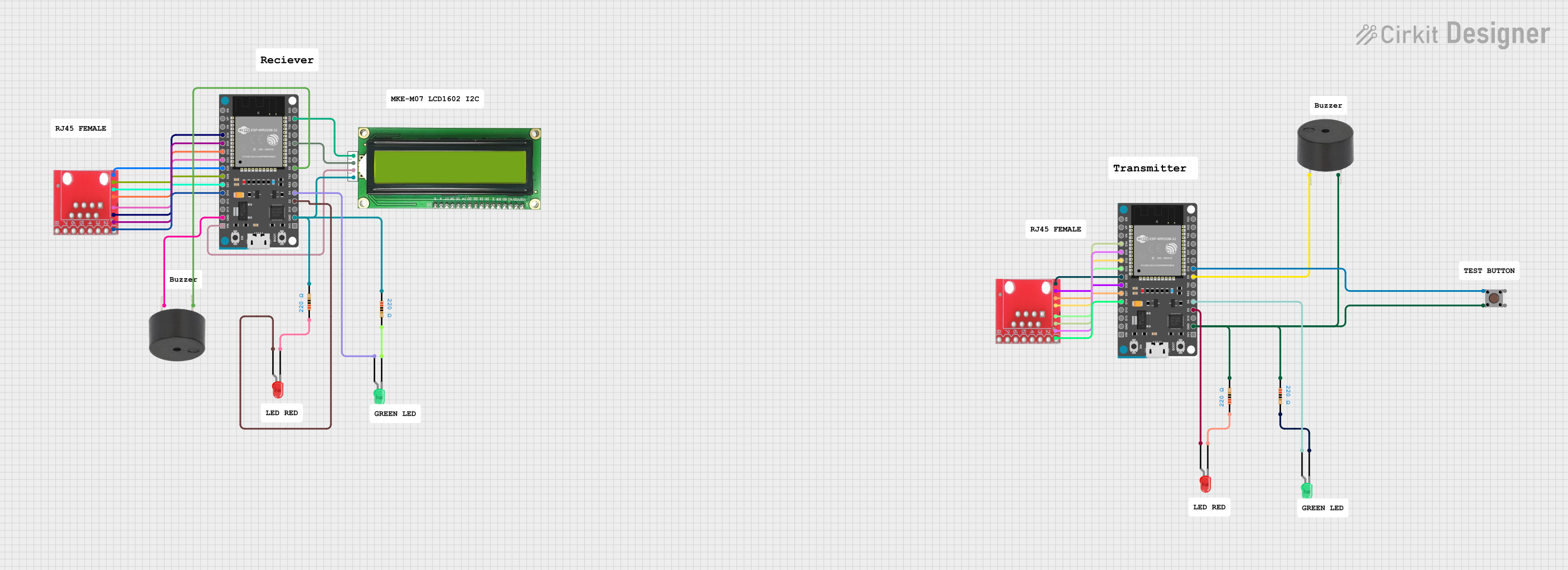
Explore Projects Built with USB Cable
Common Applications and Use Cases
- Data Transfer: Transferring files between devices, such as from a smartphone to a computer.
- Charging: Supplying power to devices like smartphones, tablets, and power banks.
- Peripheral Connectivity: Connecting devices like printers, keyboards, mice, and external storage drives.
- Embedded Systems: Used in microcontroller projects for programming and serial communication.
Technical Specifications
Key Technical Details
| Specification | Description |
|---|---|
| Connector Types | USB-A, USB-B, USB-C, Micro-USB, Mini-USB |
| Standards Supported | USB 1.1, USB 2.0, USB 3.0, USB 3.1, USB 3.2, USB4 |
| Data Transfer Rate | Up to 40 Gbps (USB4), depending on the cable and standard |
| Power Delivery | Up to 100W (20V, 5A) for USB-C with Power Delivery (PD) support |
| Cable Length | Typically ranges from 0.5m to 5m |
| Shielding | Shielded to reduce electromagnetic interference (EMI) |
Pin Configuration and Descriptions
USB-A Connector
| Pin Number | Name | Description |
|---|---|---|
| 1 | VBUS | +5V Power Supply |
| 2 | D- | Data Line (Negative) |
| 3 | D+ | Data Line (Positive) |
| 4 | GND | Ground |
USB-C Connector
| Pin Number | Name | Description |
|---|---|---|
| A1, B1 | GND | Ground |
| A4, B4 | VBUS | +5V to +20V Power Supply |
| A6, B6 | D+ | Data Line (Positive) |
| A7, B7 | D- | Data Line (Negative) |
| A8, B8 | SBU1, SBU2 | Sideband Use (Alternate Modes) |
| A2, B2 | TX1+, TX2+ | SuperSpeed Differential Pair (Transmit Positive) |
| A3, B3 | TX1-, TX2- | SuperSpeed Differential Pair (Transmit Negative) |
| A5, B5 | RX1+, RX2+ | SuperSpeed Differential Pair (Receive Positive) |
| A9, B9 | RX1-, RX2- | SuperSpeed Differential Pair (Receive Negative) |
Usage Instructions
How to Use the USB Cable in a Circuit
- Identify the Connector Type: Determine the type of USB connector required for your devices (e.g., USB-A, USB-C, Micro-USB).
- Connect the Devices: Plug the appropriate ends of the USB cable into the devices. Ensure the connectors are oriented correctly to avoid damage.
- Data Transfer: For data transfer, ensure both devices support the same USB standard (e.g., USB 3.0) for optimal performance.
- Power Delivery: When using USB-C for power delivery, verify that the cable and devices support the required voltage and current levels.
Important Considerations and Best Practices
- Cable Quality: Use high-quality cables to ensure reliable data transfer and power delivery.
- Length Limitations: Avoid using excessively long cables, as this can degrade signal quality and reduce charging efficiency.
- Compatibility: Check the USB standard compatibility of your devices and cable to ensure proper functionality.
- Avoid Overloading: Do not exceed the power rating of the cable, especially for USB-C with Power Delivery.
Example: Connecting an Arduino UNO to a Computer
A USB cable (typically USB-A to USB-B) is commonly used to connect an Arduino UNO to a computer for programming and serial communication. Below is an example of Arduino code to send data over the USB connection:
// This code sends a message over the USB serial connection to the computer
void setup() {
  Serial.begin(9600); // Initialize serial communication at 9600 baud
  while (!Serial) {
    // Wait for the serial port to connect (needed for some boards)
  }
  Serial.println("USB connection established!"); // Send a message
}

void loop() {
  Serial.println("Hello from Arduino!"); // Send data repeatedly
  delay(1000); // Wait for 1 second
}
Troubleshooting and FAQs
Common Issues and Solutions
Device Not Recognized:
- Cause: Faulty cable, incorrect driver, or unsupported USB standard.
- Solution: Test with a different cable, update drivers, or check device compatibility.
Slow Data Transfer:
- Cause: Using a lower USB standard (e.g., USB 2.0 instead of USB 3.0).
- Solution: Use a cable and devices that support higher USB standards.
Charging Issues:
- Cause: Insufficient power delivery or damaged cable.
- Solution: Use a cable rated for the required power level and check for physical damage.
Intermittent Connection:
- Cause: Loose connectors or poor cable quality.
- Solution: Ensure connectors are securely plugged in and replace the cable if necessary.
FAQs
Q: Can I use a USB 2.0 cable with a USB 3.0 device?
- A: Yes, but the data transfer rate will be limited to USB 2.0 speeds.
Q: How do I identify a USB-C cable with Power Delivery support?
- A: Look for markings or specifications indicating "PD" or check the product documentation.
Q: Is it safe to use third-party USB cables?
- A: Yes, as long as the cable meets the required specifications and is from a reputable manufacturer.