
How to Use 4-Channel Bidirectional Logic Level Shifter: Examples, Pinouts, and Specs
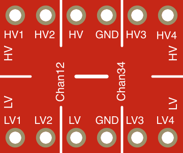
 Design with 4-Channel Bidirectional Logic Level Shifter in Cirkit Designer
Introduction
The 4-Channel Bidirectional Logic Level Shifter is a versatile device designed to facilitate voltage level conversion between two different logic levels. It enables seamless communication between components operating at different voltage levels, such as 3.3V and 5V systems. This component is particularly useful in mixed-voltage environments where microcontrollers, sensors, or other peripherals need to interface with each other.
Explore Projects Built with 4-Channel Bidirectional Logic Level Shifter
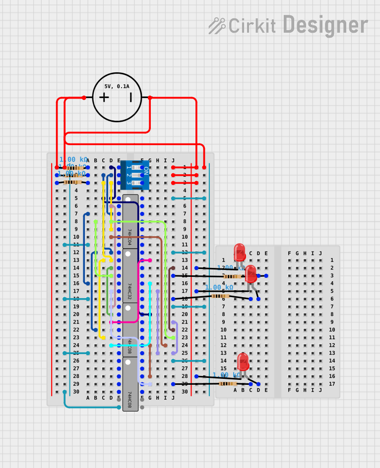 Open Project in Cirkit Designer
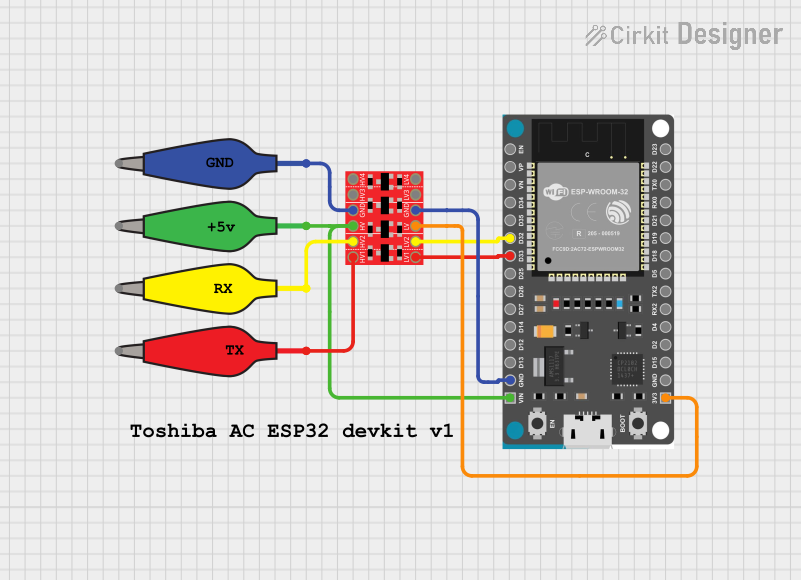 Open Project in Cirkit Designer
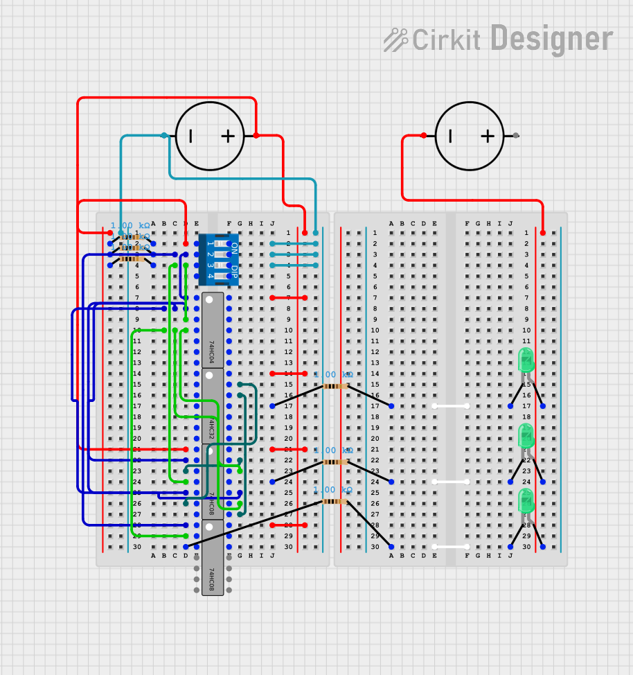 Open Project in Cirkit Designer
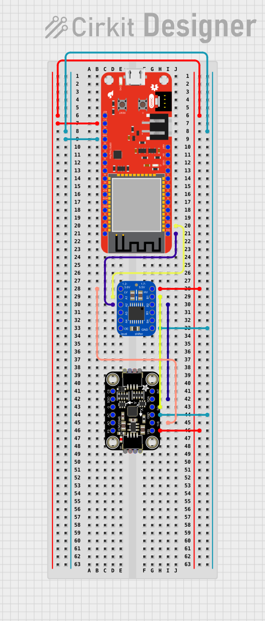 Open Project in Cirkit Designer
Explore Projects Built with 4-Channel Bidirectional Logic Level Shifter
Open Project in Cirkit DesignerOpen Project in Cirkit DesignerOpen Project in Cirkit DesignerOpen Project in Cirkit DesignerCommon Applications and Use Cases
- Interfacing 3.3V microcontrollers (e.g., ESP32, Raspberry Pi) with 5V peripherals (e.g., Arduino, sensors).
- Communication between I2C, SPI, or UART devices operating at different voltage levels.
- Voltage level translation in mixed-voltage circuits.
- Prototyping and development of embedded systems.
Technical Specifications
The following table outlines the key technical details of the 4-Channel Bidirectional Logic Level Shifter:
| Parameter | Value |
|---|---|
| Operating Voltage (High Side) | 3.3V to 5.5V |
| Operating Voltage (Low Side) | 1.8V to 3.3V |
| Number of Channels | 4 |
| Data Direction | Bidirectional |
| Maximum Data Rate | ~100 kHz (I2C) or higher for SPI |
| Operating Temperature | -40°C to +85°C |
| Dimensions | ~15mm x 15mm x 3mm |
Pin Configuration and Descriptions
The 4-Channel Bidirectional Logic Level Shifter typically has the following pinout:
| Pin Name | Description |
|---|---|
| HV (High Voltage) | Connect to the high-side voltage source (e.g., 5V). |
| LV (Low Voltage) | Connect to the low-side voltage source (e.g., 3.3V). |
| GND | Ground connection (common ground for both voltage levels). |
| TX1, TX2, TX3, TX4 | High-side data pins for channels 1 to 4. |
| RX1, RX2, RX3, RX4 | Low-side data pins for channels 1 to 4. |
Usage Instructions
How to Use the Component in a Circuit
Power Connections:
- Connect the
HVpin to the high-side voltage source (e.g., 5V). - Connect the
LVpin to the low-side voltage source (e.g., 3.3V). - Connect the
GNDpin to the common ground of the circuit.
- Connect the
Data Connections:
- Connect the high-voltage logic signals to the
TXpins (e.g., TX1, TX2). - Connect the low-voltage logic signals to the corresponding
RXpins (e.g., RX1, RX2). - The level shifter will automatically translate signals bidirectionally.
- Connect the high-voltage logic signals to the
I2C Example:
- For I2C communication, connect the
SCLandSDAlines of the high-voltage side toTX1andTX2, respectively. - Connect the
SCLandSDAlines of the low-voltage side toRX1andRX2, respectively.
- For I2C communication, connect the
Important Considerations and Best Practices
- Ensure that the
HVandLVvoltage levels are within the specified operating range. - Use pull-up resistors on the I2C lines if they are not already present in your circuit.
- Avoid exceeding the maximum data rate to ensure reliable communication.
- Always connect the
GNDpin to the common ground of the circuit to prevent communication errors.
Example: Connecting to an Arduino UNO
Below is an example of using the 4-Channel Bidirectional Logic Level Shifter to interface a 3.3V sensor with a 5V Arduino UNO:
Circuit Connections
- Connect the
HVpin to the Arduino's 5V pin. - Connect the
LVpin to the sensor's 3.3V pin. - Connect the
GNDpin to the common ground. - Connect the sensor's
SDAandSCLpins toRX1andRX2, respectively. - Connect the Arduino's
SDAandSCLpins toTX1andTX2, respectively.
Arduino Code Example
#include <Wire.h> // Include the Wire library for I2C communication

void setup() {
  Wire.begin(); // Initialize I2C communication
  Serial.begin(9600); // Start serial communication for debugging

  // Example: Communicate with a sensor at I2C address 0x40
  Wire.beginTransmission(0x40); // Begin communication with the sensor
  Wire.write(0x00); // Send a command or register address
  Wire.endTransmission(); // End the transmission
}

void loop() {
  Wire.requestFrom(0x40, 2); // Request 2 bytes of data from the sensor

  if (Wire.available() == 2) { // Check if 2 bytes are available
    int data = Wire.read() << 8 | Wire.read(); // Read and combine the data
    Serial.println(data); // Print the data to the Serial Monitor
  }

  delay(1000); // Wait for 1 second before the next reading
}
Troubleshooting and FAQs
Common Issues Users Might Face
No Communication Between Devices:
- Ensure that the
HVandLVpins are connected to the correct voltage levels. - Verify that the
GNDpin is connected to the common ground of the circuit. - Check for loose or incorrect wiring.
- Ensure that the
Data Corruption or Noise:
- Use appropriate pull-up resistors on the I2C or SPI lines.
- Ensure that the data rate does not exceed the maximum supported by the level shifter.
Overheating or Damage:
- Verify that the voltage levels do not exceed the specified operating range.
- Avoid short circuits or incorrect connections.
Solutions and Tips for Troubleshooting
- Use a multimeter to check voltage levels at the
HV,LV, andGNDpins. - Test the circuit with a simple setup (e.g., one channel) before scaling up.
- Refer to the datasheet of the connected devices to ensure compatibility with the level shifter.
By following this documentation, you can effectively use the 4-Channel Bidirectional Logic Level Shifter in your projects and troubleshoot common issues with ease.