How to Use PowerBoost 500 Basic Pad: Examples, Pinouts, and Specs
Introduction
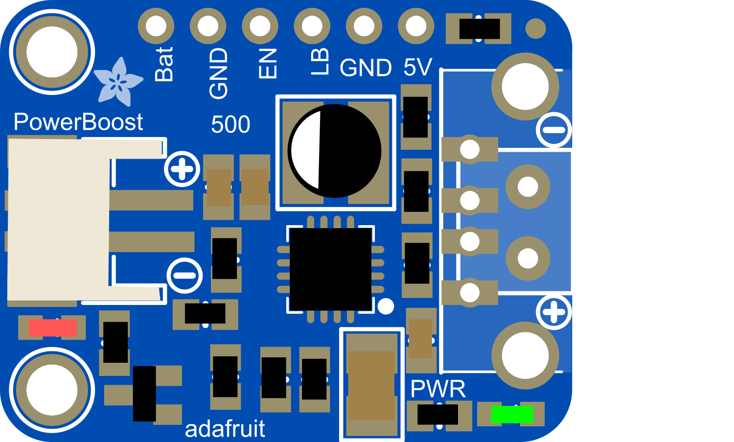
The PowerBoost 500 Basic Pad is a versatile and compact power supply module designed to step up voltage to a regulated 5V output from a lower voltage source, typically a single-cell lithium-polymer (LiPo) battery. This makes it ideal for portable electronics, wearables, and projects where USB power is necessary. The PowerBoost 500 Basic Pad is particularly useful for powering devices that require a stable 5V supply when only a lower voltage battery is available.
Explore Projects Built with PowerBoost 500 Basic Pad

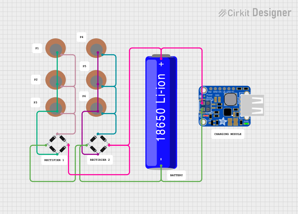
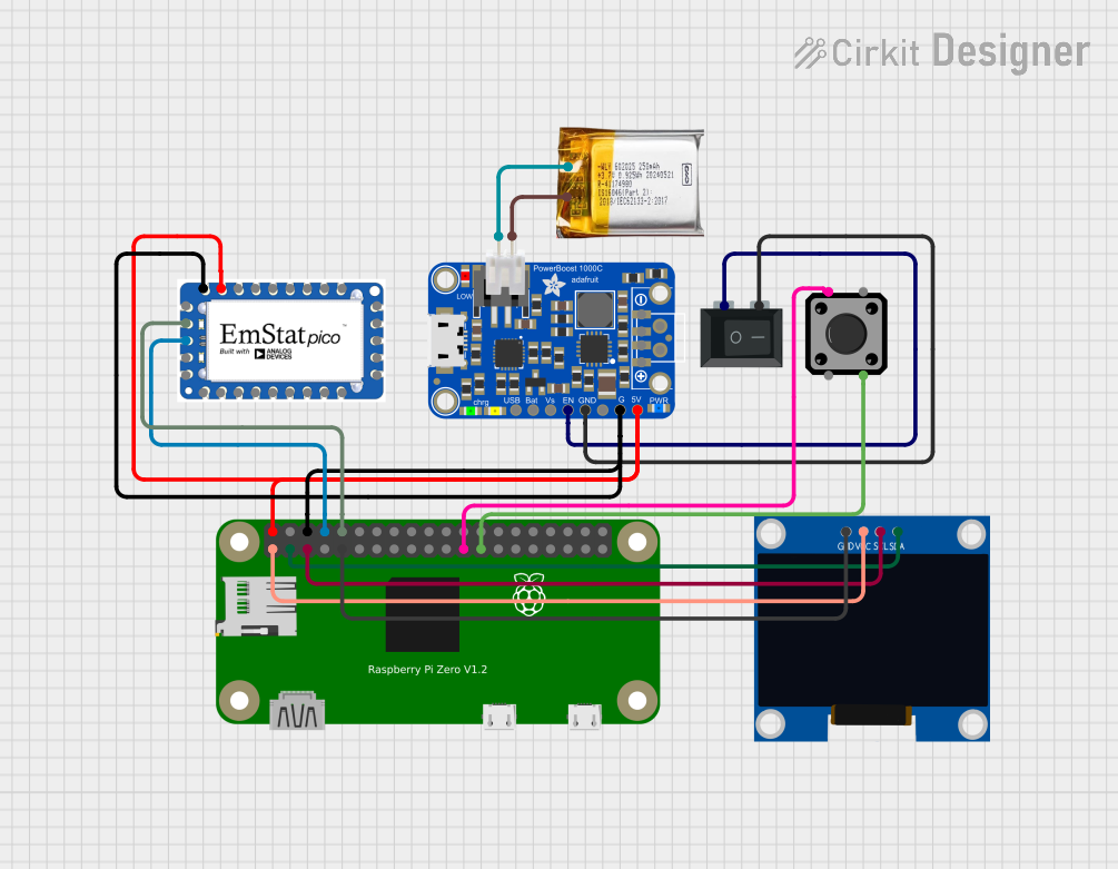
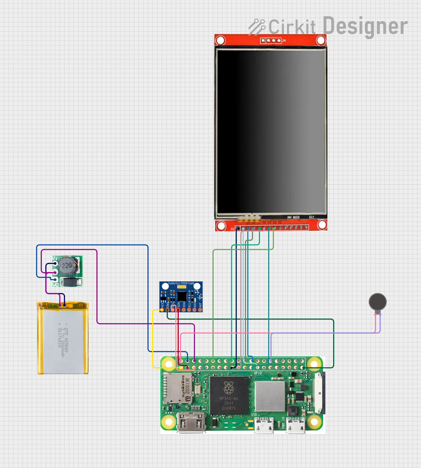
Explore Projects Built with PowerBoost 500 Basic Pad
Common Applications and Use Cases
- Portable USB chargers
- Battery-powered Raspberry Pi projects
- Wearable electronics
- DIY USB-powered gadgets and toys
Technical Specifications
Key Technical Details
- Input Voltage: 1.8V to 5.5V
- Output Voltage: 5V regulated
- Output Current: Up to 500mA
- Efficiency: 85-95% typical
- Quiescent Current: 5mA typical
Pin Configuration and Descriptions
| Pin Name | Description |
|---|---|
| VIN | Input voltage (1.8V to 5.5V) |
| GND | Ground connection |
| 5V | Regulated 5V output |
| EN | Enable pin (ground to disable) |
Usage Instructions
How to Use the Component in a Circuit
- Power Input: Connect the positive terminal of your battery or power source to the VIN pin, and the negative terminal to the GND pin.
- Power Output: Connect the 5V and GND pins to your project or USB connector to deliver a regulated 5V supply.
- Enable Pin: Optionally, connect the EN pin to a digital output of a microcontroller or a switch to ground to enable or disable the power output.
Important Considerations and Best Practices
- Ensure that the input voltage does not exceed 5.5V to prevent damage to the PowerBoost 500 Basic Pad.
- Do not draw more than 500mA from the 5V output to maintain voltage regulation and prevent overheating.
- If using the EN pin, ensure that it is either actively driven or tied to VIN for normal operation.
- For battery-powered projects, consider adding a low-battery cutoff circuit to prevent deep discharge of the LiPo battery.
Troubleshooting and FAQs
Common Issues Users Might Face
- Output voltage is lower than 5V: Check if the input voltage is within the specified range and that the current draw is not exceeding 500mA.
- PowerBoost 500 Basic Pad is overheating: Ensure that the current draw is within limits and that there is adequate ventilation around the component.
- No output when battery is connected: Verify that the battery is charged and that the EN pin is not inadvertently grounded.
Solutions and Tips for Troubleshooting
- If the output voltage drops under load, consider using a battery with a higher capacity or a lower resistance path to the VIN pin.
- For overheating issues, reduce the load or improve airflow around the PowerBoost 500 Basic Pad.
- If the EN pin is accidentally grounded, the PowerBoost 500 Basic Pad will be disabled. Check the connections and ensure that the EN pin is either left floating or connected to VIN for normal operation.
FAQs
Q: Can I use the PowerBoost 500 Basic Pad to charge a LiPo battery? A: No, the PowerBoost 500 Basic Pad is designed to boost voltage and does not include charging circuitry.
Q: Is it possible to use multiple PowerBoost 500 Basic Pads in parallel to increase current output? A: It is not recommended to use boost converters in parallel due to potential issues with load sharing and synchronization.
Q: How can I connect this to an Arduino UNO? A: You can connect the 5V and GND outputs from the PowerBoost 500 Basic Pad to the 5V and GND pins on the Arduino UNO to power it.
Example Code for Arduino UNO
// This example demonstrates how to control the PowerBoost 500 Basic Pad's EN pin using an Arduino UNO.

const int enablePin = 7; // Connect the EN pin of PowerBoost to digital pin 7 on Arduino

void setup() {
  pinMode(enablePin, OUTPUT); // Set the enable pin as an output
  digitalWrite(enablePin, HIGH); // Enable the PowerBoost 500 Basic Pad
}

void loop() {
  // Your code here to control the PowerBoost 500 Basic Pad
  // For example, to turn off the power supply:
  // digitalWrite(enablePin, LOW);

  // Remember to limit your comments to 80 characters per line
}
Remember to adjust the enablePin variable to match the actual pin you've connected the EN pin to on your Arduino UNO.