How to Use 3 position dip switch: Examples, Pinouts, and Specs

Introduction
A 3-position DIP (Dual In-line Package) switch is a small, manual electrical switch packaged in a standard DIP form. It consists of three individual switches that can be toggled between an ON and OFF position, allowing for binary setting of three separate positions. This component is widely used for hardware configuration, mode selection, and setting options in electronic devices without the need for software intervention.
Explore Projects Built with 3 position dip switch

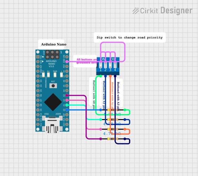

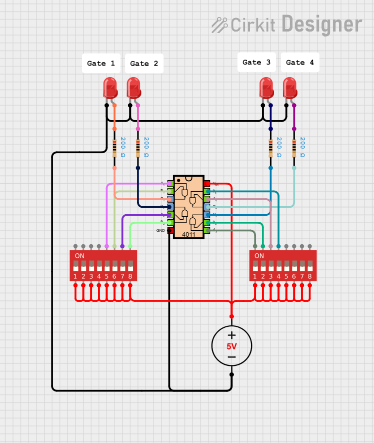
Explore Projects Built with 3 position dip switch
Common Applications and Use Cases
- Setting operating modes for electronic devices
- Configuring hardware parameters
- Selecting options on printed circuit boards (PCBs)
- User interface for setting preferences in electronic kits
- Prototyping and development, often with microcontrollers like Arduino
Technical Specifications
Key Technical Details
- Voltage Rating: Typically 3.3V to 5V
- Current Rating: Usually around 25mA per switch
- Contact Resistance: Maximum 50 mΩ initial
- Insulation Resistance: Minimum 100 MΩ at 500V DC
- Dielectric Strength: Typically 500V AC for 1 minute
- Operating Temperature Range: -40°C to +85°C
Pin Configuration and Descriptions
| Pin Number | Description | State |
|---|---|---|
| 1 | Switch 1 (S1) | ON/OFF |
| 2 | Switch 1 (S1) | ON/OFF |
| 3 | Switch 2 (S2) | ON/OFF |
| 4 | Switch 2 (S2) | ON/OFF |
| 5 | Switch 3 (S3) | ON/OFF |
| 6 | Switch 3 (S3) | ON/OFF |
Note: Pins are paired for each switch position, with one pin typically serving as the common terminal and the other as the normally open (NO) contact.
Usage Instructions
How to Use the Component in a Circuit
- Mounting: Insert the DIP switch into the PCB with the correct orientation.
- Wiring: Connect the common terminal of each switch to the circuit's ground or Vcc, depending on the logic level desired when the switch is in the ON position.
- Configuration: Set each switch to the desired ON or OFF position to represent the binary configuration needed for your application.
Important Considerations and Best Practices
- Ensure the DIP switch is powered off before changing positions to prevent short circuits or damage.
- Avoid applying excessive force to the switch toggles to prevent mechanical damage.
- Use a small tool like a screwdriver to change switch positions if they are too small for fingers.
- Verify the switch positions before powering up the circuit to ensure the correct configuration is set.
Troubleshooting and FAQs
Common Issues
- Switch not responding: Ensure that the switch is properly soldered to the PCB and there are no cold solder joints.
- Incorrect logic level: Check the connection of the common terminal to ensure it's connected to the correct voltage level (ground or Vcc).
Solutions and Tips for Troubleshooting
- If a switch seems non-responsive, verify the continuity with a multimeter in the ON and OFF positions.
- Ensure that the DIP switch is rated for the voltage and current levels in your application to prevent damage.
FAQs
Q: Can I use a 3-position DIP switch with an Arduino? A: Yes, DIP switches can be used with an Arduino for input selection. Each switch can be read as a digital input.
Q: What is the typical life expectancy of a DIP switch? A: DIP switches typically have a mechanical life of several thousand cycles, but this can vary based on the manufacturer and usage conditions.
Q: How do I clean a DIP switch? A: Use a contact cleaner spray designed for electronic components. Avoid using water or any conductive liquids.
Example Arduino Code
// Define the Arduino pins connected to the DIP switch
const int switch1Pin = 2; // Switch 1
const int switch2Pin = 3; // Switch 2
const int switch3Pin = 4; // Switch 3

void setup() {
  // Set the switch pins as input
  pinMode(switch1Pin, INPUT_PULLUP);
  pinMode(switch2Pin, INPUT_PULLUP);
  pinMode(switch3Pin, INPUT_PULLUP);
}

void loop() {
  // Read the state of each switch
  bool switch1State = digitalRead(switch1Pin) == LOW; // Active LOW
  bool switch2State = digitalRead(switch2Pin) == LOW; // Active LOW
  bool switch3State = digitalRead(switch3Pin) == LOW; // Active LOW

  // Implement logic based on the switch states
  // ...
}
Note: The INPUT_PULLUP mode is used to enable the internal pull-up resistors. This configuration assumes that the common terminal of the DIP switch is connected to ground, resulting in an active LOW when the switch is in the ON position.