Cirkit Designer Logo
Cirkit Designer
Your all-in-one circuit design IDE
Home / 
Component Documentation

How to Use LILYGO T-Higrow ESP32: Examples, Pinouts, and Specs

Image of LILYGO T-Higrow ESP32
Cirkit Designer LogoDesign with LILYGO T-Higrow ESP32 in Cirkit Designer

Introduction

The LILYGO T-Higrow ESP32 is a versatile development board designed for Internet of Things (IoT) applications. It is powered by the ESP32 microcontroller, which features dual-core processing, built-in Wi-Fi, and Bluetooth capabilities. The T-Higrow board is equipped with various sensors, including a capacitive soil moisture sensor, temperature and humidity sensor, and a battery management system, making it ideal for environmental monitoring and smart agriculture projects.

Explore Projects Built with LILYGO T-Higrow ESP32

Use Cirkit Designer to design, explore, and prototype these projects online. Some projects support real-time simulation. Click "Open Project" to start designing instantly!
Cellular-Connected ESP32-CAM with Real-Time Clock and Isolated Control
Image of LRCM PHASE 2 PRO: A project utilizing LILYGO T-Higrow ESP32 in a practical application
This circuit integrates a LilyGo-SIM7000G module with an RTC DS3231 for timekeeping, interfaced via I2C (SCL and SDA lines). An 8-Channel OPTO-COUPLER is used to isolate and interface external signals with the LilyGo-SIM7000G's GPIOs. Power is managed by a Buck converter, which steps down voltage from a DC Power Source to supply the ESP32-CAM and LilyGo-SIM7000G modules, as well as the OPTO-COUPLER.
Cirkit Designer LogoOpen Project in Cirkit Designer
ESP32-Based NTP Clock with DHT22 Temperature Sensor and WS2812 LED Matrix Display
Image of date time and temperature display : A project utilizing LILYGO T-Higrow ESP32 in a practical application
This circuit features an ESP32 Devkit V1 microcontroller connected to a DHT22 temperature and humidity sensor and an 8x8 WS2812 RGB LED matrix. The ESP32 reads temperature data from the DHT22 sensor and displays the current date, time, and temperature on the LED matrix, with date and time synchronized via NTP (Network Time Protocol). The ESP32 provides power to both the DHT22 and the LED matrix and communicates with the DHT22 via GPIO 4 and with the LED matrix via GPIO 5.
Cirkit Designer LogoOpen Project in Cirkit Designer
ESP32 Mini-Based Smart Timekeeper with OLED Display and Battery Charging
Image of RM Gloves: A project utilizing LILYGO T-Higrow ESP32 in a practical application
This circuit features an ESP32 Mini microcontroller as its core, interfaced with a 0.96" OLED display and a DS3231 Real-Time Clock (RTC) for timekeeping and display purposes. A TP4056 module is used for charging a LiPoly battery, which powers the system through an LM2596 voltage regulator and an AMS1117-3.3 voltage regulator to step down and stabilize the voltage for the ESP32 and peripherals. User inputs are captured through a rotary potentiometer and a red pushbutton, which are connected to the ESP32's GPIOs for control and reset functionality.
Cirkit Designer LogoOpen Project in Cirkit Designer
ESP32C3 and LoRa-Enabled Environmental Sensing Node
Image of temperature_KA: A project utilizing LILYGO T-Higrow ESP32 in a practical application
This circuit features an ESP32C3 Supermini microcontroller connected to a LORA_RA02 module and a DHT11 temperature and humidity sensor. The ESP32C3 handles communication with the LORA module via SPI (using GPIO05, GPIO06, GPIO10, and GPIO04 for MISO, MOSI, NSS, and SCK respectively) and GPIO01 and GPIO02 for additional control signals. The DHT11 sensor is interfaced through GPIO03 for data reading, and all components share a common power supply through the 3.3V and GND pins.
Cirkit Designer LogoOpen Project in Cirkit Designer

Explore Projects Built with LILYGO T-Higrow ESP32

Use Cirkit Designer to design, explore, and prototype these projects online. Some projects support real-time simulation. Click "Open Project" to start designing instantly!
Image of LRCM PHASE 2 PRO: A project utilizing LILYGO T-Higrow ESP32 in a practical application
Cellular-Connected ESP32-CAM with Real-Time Clock and Isolated Control
This circuit integrates a LilyGo-SIM7000G module with an RTC DS3231 for timekeeping, interfaced via I2C (SCL and SDA lines). An 8-Channel OPTO-COUPLER is used to isolate and interface external signals with the LilyGo-SIM7000G's GPIOs. Power is managed by a Buck converter, which steps down voltage from a DC Power Source to supply the ESP32-CAM and LilyGo-SIM7000G modules, as well as the OPTO-COUPLER.
Cirkit Designer LogoOpen Project in Cirkit Designer
Image of date time and temperature display : A project utilizing LILYGO T-Higrow ESP32 in a practical application
ESP32-Based NTP Clock with DHT22 Temperature Sensor and WS2812 LED Matrix Display
This circuit features an ESP32 Devkit V1 microcontroller connected to a DHT22 temperature and humidity sensor and an 8x8 WS2812 RGB LED matrix. The ESP32 reads temperature data from the DHT22 sensor and displays the current date, time, and temperature on the LED matrix, with date and time synchronized via NTP (Network Time Protocol). The ESP32 provides power to both the DHT22 and the LED matrix and communicates with the DHT22 via GPIO 4 and with the LED matrix via GPIO 5.
Cirkit Designer LogoOpen Project in Cirkit Designer
Image of RM Gloves: A project utilizing LILYGO T-Higrow ESP32 in a practical application
ESP32 Mini-Based Smart Timekeeper with OLED Display and Battery Charging
This circuit features an ESP32 Mini microcontroller as its core, interfaced with a 0.96" OLED display and a DS3231 Real-Time Clock (RTC) for timekeeping and display purposes. A TP4056 module is used for charging a LiPoly battery, which powers the system through an LM2596 voltage regulator and an AMS1117-3.3 voltage regulator to step down and stabilize the voltage for the ESP32 and peripherals. User inputs are captured through a rotary potentiometer and a red pushbutton, which are connected to the ESP32's GPIOs for control and reset functionality.
Cirkit Designer LogoOpen Project in Cirkit Designer
Image of temperature_KA: A project utilizing LILYGO T-Higrow ESP32 in a practical application
ESP32C3 and LoRa-Enabled Environmental Sensing Node
This circuit features an ESP32C3 Supermini microcontroller connected to a LORA_RA02 module and a DHT11 temperature and humidity sensor. The ESP32C3 handles communication with the LORA module via SPI (using GPIO05, GPIO06, GPIO10, and GPIO04 for MISO, MOSI, NSS, and SCK respectively) and GPIO01 and GPIO02 for additional control signals. The DHT11 sensor is interfaced through GPIO03 for data reading, and all components share a common power supply through the 3.3V and GND pins.
Cirkit Designer LogoOpen Project in Cirkit Designer

Common Applications and Use Cases

  • Smart agriculture and soil monitoring
  • Environmental data logging
  • IoT-based weather stations
  • Home automation systems
  • Educational projects and prototyping

Technical Specifications

The following table outlines the key technical details of the LILYGO T-Higrow ESP32:

Parameter Specification
Microcontroller ESP32 (dual-core, 32-bit, Xtensa LX6)
Clock Speed Up to 240 MHz
Flash Memory 4 MB
Connectivity Wi-Fi 802.11 b/g/n, Bluetooth 4.2
Power Supply 3.7V LiPo battery or USB (5V)
Battery Management Integrated charging circuit for LiPo batteries
Sensors Capacitive soil moisture sensor, DHT11 (temperature and humidity)
GPIO Pins 10 (configurable for digital or analog input/output)
Operating Voltage 3.3V
Dimensions 50mm x 25mm

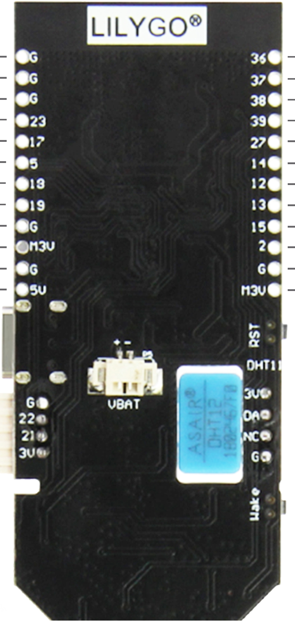
Pin Configuration and Descriptions

The T-Higrow ESP32 features a compact pinout. Below is the pin configuration:

Pin Name Description
1 GND Ground
2 3V3 3.3V power output
3 GPIO0 General-purpose I/O (used for boot mode selection)
4 GPIO2 General-purpose I/O
5 GPIO4 General-purpose I/O (connected to soil moisture sensor)
6 GPIO5 General-purpose I/O
7 GPIO12 General-purpose I/O
8 GPIO13 General-purpose I/O
9 GPIO14 General-purpose I/O
10 GPIO15 General-purpose I/O
11 BAT Battery voltage monitoring
12 USB USB power input

Usage Instructions

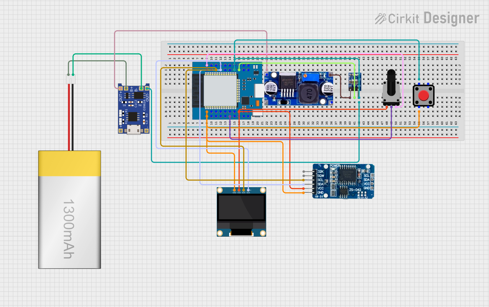
How to Use the Component in a Circuit

  1. Powering the Board:

    • Connect a 3.7V LiPo battery to the battery connector, or power the board via the USB port (5V).
    • Ensure the battery is properly charged if using battery power.
  2. Connecting Sensors:

    • The capacitive soil moisture sensor is pre-wired to GPIO4.
    • The DHT11 temperature and humidity sensor is integrated and does not require additional connections.
  3. Programming the Board:

    • Use the Arduino IDE or ESP-IDF to program the ESP32.
    • Install the necessary ESP32 board definitions in the Arduino IDE.
    • Connect the board to your computer via USB and select the appropriate COM port.
  4. Uploading Code:

    • Press and hold the "BOOT" button while clicking "Upload" in the Arduino IDE to enter programming mode.

Important Considerations and Best Practices

  • Power Supply: Always use a stable power source to avoid unexpected resets or malfunctions.
  • Moisture Sensor: Avoid prolonged exposure of the soil moisture sensor to water to prevent corrosion.
  • Battery Management: Use only compatible LiPo batteries to ensure safe operation.
  • Wi-Fi and Bluetooth: Avoid using both Wi-Fi and Bluetooth simultaneously for power-sensitive applications.

Example Code for Arduino IDE

Below is an example code snippet to read data from the soil moisture sensor and DHT11 sensor:

#include <DHT.h>

// Define pin connections
#define SOIL_MOISTURE_PIN 4  // GPIO4 for soil moisture sensor
#define DHT_PIN 5            // GPIO5 for DHT11 sensor
#define DHT_TYPE DHT11       // Define the type of DHT sensor

DHT dht(DHT_PIN, DHT_TYPE);

void setup() {
  Serial.begin(115200);  // Initialize serial communication
  dht.begin();           // Initialize DHT sensor
  pinMode(SOIL_MOISTURE_PIN, INPUT);  // Set soil moisture pin as input
}

void loop() {
  // Read soil moisture value
  int soilMoistureValue = analogRead(SOIL_MOISTURE_PIN);
  Serial.print("Soil Moisture: ");
  Serial.println(soilMoistureValue);

  // Read temperature and humidity
  float temperature = dht.readTemperature();
  float humidity = dht.readHumidity();

  // Check if readings are valid
  if (isnan(temperature) || isnan(humidity)) {
    Serial.println("Failed to read from DHT sensor!");
  } else {
    Serial.print("Temperature: ");
    Serial.print(temperature);
    Serial.println(" °C");
    Serial.print("Humidity: ");
    Serial.print(humidity);
    Serial.println(" %");
  }

  delay(2000);  // Wait 2 seconds before the next reading
}

Troubleshooting and FAQs

Common Issues and Solutions

  1. Board Not Detected by Computer:

    • Ensure the USB cable is functional and supports data transfer.
    • Verify that the correct COM port is selected in the Arduino IDE.
  2. Failed to Upload Code:

    • Press and hold the "BOOT" button while uploading the code.
    • Check that the correct board and port are selected in the Arduino IDE.
  3. Incorrect Sensor Readings:

    • Ensure the sensors are properly connected and not damaged.
    • Verify that the soil moisture sensor is not submerged in water for extended periods.
  4. Wi-Fi Connection Issues:

    • Check the Wi-Fi credentials in your code.
    • Ensure the Wi-Fi network is within range and operational.

FAQs

  • Can I use the T-Higrow ESP32 with other IoT platforms?
    Yes, the board is compatible with platforms like Blynk, MQTT, and ThingSpeak.

  • What is the maximum range of the Wi-Fi module?
    The ESP32's Wi-Fi range is approximately 30 meters indoors and 100 meters outdoors, depending on environmental factors.

  • Can I power the board directly with a 5V power supply?
    Yes, you can power the board via the USB port using a 5V power supply.

  • Is the board compatible with MicroPython?
    Yes, the T-Higrow ESP32 supports MicroPython in addition to the Arduino IDE and ESP-IDF.