How to Use START PUSH BUTTON: Examples, Pinouts, and Specs
Introduction
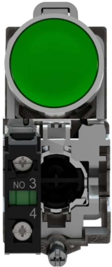
The START PUSH BUTTON (Manufacturer: Schneider, Part ID: XB4-BA31) is a momentary switch designed to complete a circuit when pressed. It is commonly used to initiate a function or process in electronic devices, industrial control systems, and automation applications. This robust and reliable component is ideal for environments requiring frequent operation and high durability.
Explore Projects Built with START PUSH BUTTON
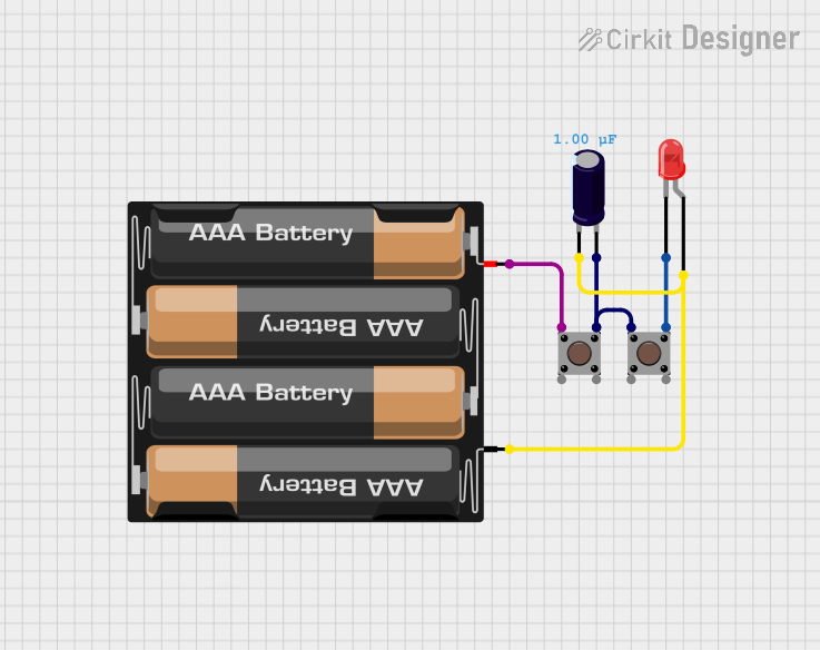

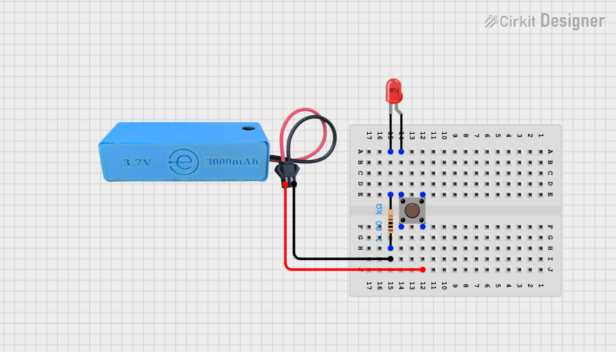
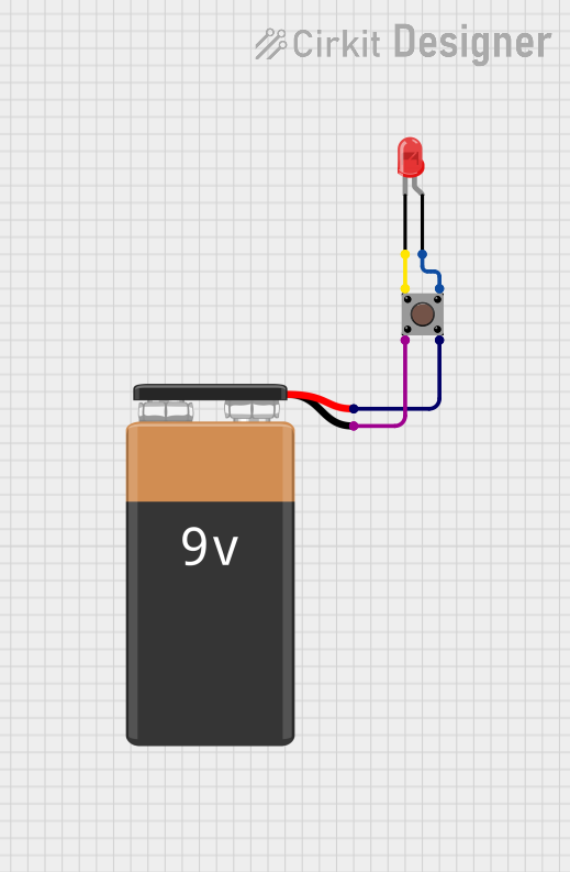
Explore Projects Built with START PUSH BUTTON
Common Applications
- Industrial machinery start/stop controls
- Automation systems
- Consumer electronics
- Robotics and mechatronics
- Emergency or manual override systems
Technical Specifications
Key Technical Details
| Parameter | Specification |
|---|---|
| Manufacturer | Schneider |
| Part ID | XB4-BA31 |
| Switch Type | Momentary Push Button |
| Contact Configuration | Normally Open (NO) |
| Operating Voltage | Up to 600V AC/DC |
| Current Rating | 10A |
| Mechanical Durability | 1,000,000 cycles |
| Mounting Style | Panel Mount |
| Actuator Color | Green |
| Actuator Type | Round |
| Terminal Type | Screw Terminals |
| Operating Temperature | -25°C to +70°C |
| IP Rating | IP66 (Dust-tight and water-resistant) |
Pin Configuration and Descriptions
The XB4-BA31 push button has screw terminals for connecting wires. Below is the terminal configuration:
| Terminal Label | Description |
|---|---|
| NO | Normally Open contact (connects when pressed) |
| COM | Common terminal for the circuit |
Usage Instructions
How to Use the Component in a Circuit
Mounting the Push Button:
- Drill a 22mm diameter hole in the panel where the push button will be installed.
- Insert the push button into the hole and secure it using the provided mounting hardware.
Wiring the Push Button:
- Connect the COM terminal to the power source or ground, depending on your circuit design.
- Connect the NO terminal to the load or control input of the device you want to activate.
- Tighten the screw terminals to ensure a secure connection.
Testing the Circuit:
- Power on the circuit and press the push button. The circuit should complete, activating the connected device or function.
- Release the button to return the circuit to its default state.
Important Considerations and Best Practices
- Ensure the operating voltage and current do not exceed the component's rated specifications.
- Use appropriate wire gauges for the current rating to prevent overheating or damage.
- For outdoor or harsh environments, ensure the panel and wiring are sealed to maintain the IP66 rating.
- Regularly inspect the push button for wear and tear, especially in high-use applications.
Example: Connecting to an Arduino UNO
The START PUSH BUTTON can be used with an Arduino UNO to detect button presses. Below is an example circuit and code:
Circuit Setup
- Connect the COM terminal to the Arduino's GND pin.
- Connect the NO terminal to a digital input pin (e.g., pin 2) on the Arduino.
- Use a pull-down resistor (10kΩ) between the digital input pin and GND to ensure a stable signal.
Arduino Code
// Define the pin connected to the push button
const int buttonPin = 2;

// Variable to store the button state
int buttonState = 0;

void setup() {
  // Set the button pin as input
  pinMode(buttonPin, INPUT);

  // Initialize serial communication for debugging
  Serial.begin(9600);
}

void loop() {
  // Read the state of the push button
  buttonState = digitalRead(buttonPin);

  // Check if the button is pressed
  if (buttonState == HIGH) {
    // Print a message to the serial monitor
    Serial.println("Button Pressed!");
  } else {
    // Print a message when the button is not pressed
    Serial.println("Button Released!");
  }

  // Add a small delay to debounce the button
  delay(50);
}
Troubleshooting and FAQs
Common Issues and Solutions
Button Does Not Activate the Circuit
- Cause: Loose or incorrect wiring.
- Solution: Double-check the connections to the COM and NO terminals. Ensure the wires are securely fastened.
Button Sticks or Fails to Return to Default State
- Cause: Mechanical wear or debris in the actuator.
- Solution: Clean the button mechanism and inspect for damage. Replace the button if necessary.
Intermittent Operation
- Cause: Poor contact or insufficient pull-down resistor.
- Solution: Use a 10kΩ pull-down resistor and ensure the terminals are clean and properly connected.
Button Does Not Work with Arduino
- Cause: Incorrect pin configuration or missing pull-down resistor.
- Solution: Verify the wiring and ensure the Arduino code matches the circuit setup.
FAQs
Q: Can the XB4-BA31 be used in outdoor applications?
A: Yes, the push button has an IP66 rating, making it suitable for outdoor use when properly installed.
Q: Is the push button available in other colors?
A: Yes, Schneider offers the XB4 series in various actuator colors for different applications.
Q: Can this push button handle high-current loads directly?
A: The XB4-BA31 is rated for up to 10A. For higher currents, use a relay or contactor in conjunction with the push button.
Q: How do I replace a damaged push button?
A: Disconnect the power, remove the mounting hardware, and replace the button with a new XB4-BA31. Reconnect the wiring and test the circuit.