Cirkit Designer Logo
Cirkit Designer
Your all-in-one circuit design IDE
Home / 
Component Documentation

How to Use Polar Heart Rate Monitor Interface: Examples, Pinouts, and Specs

Image of Polar Heart Rate Monitor Interface
Cirkit Designer LogoDesign with Polar Heart Rate Monitor Interface in Cirkit Designer

Introduction

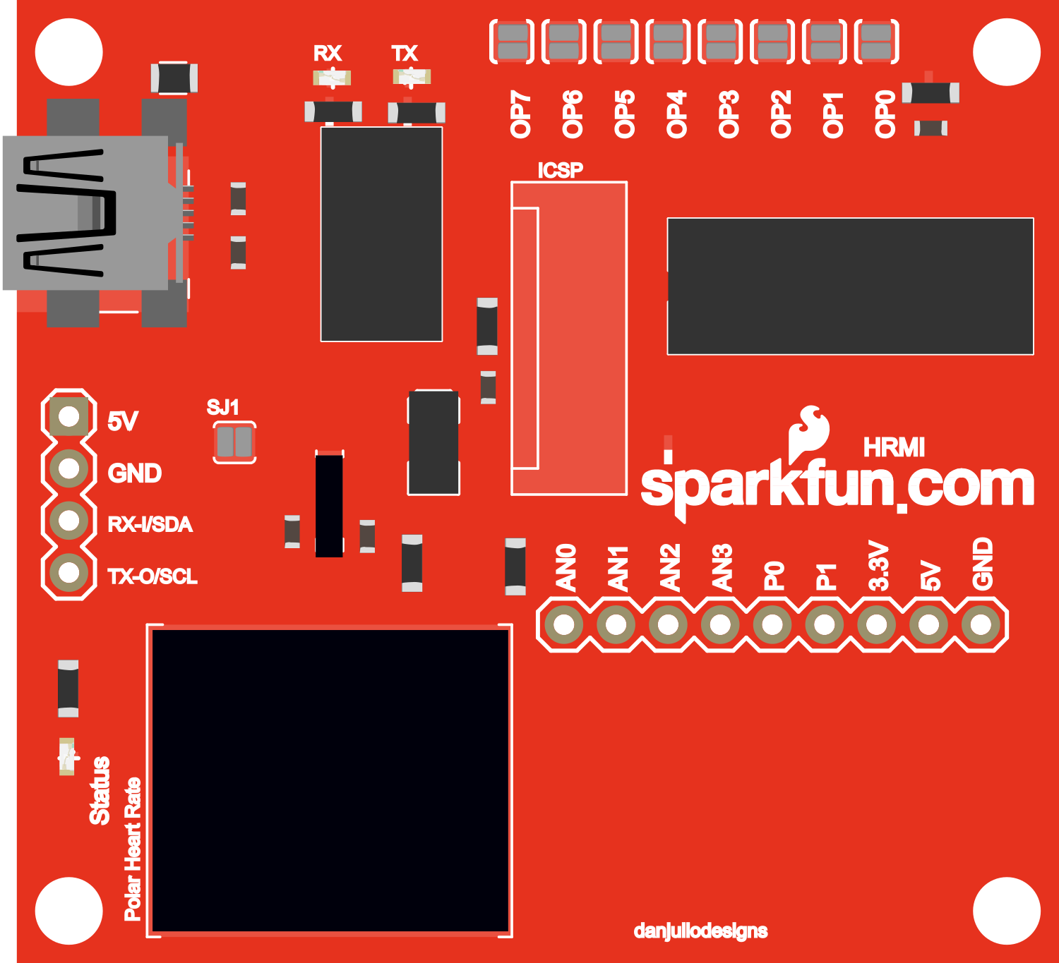
The Polar Heart Rate Monitor Interface is an electronic device designed to facilitate the integration of Polar heart rate sensors with various electronic systems, such as microcontrollers and computers. This interface is commonly used in fitness tracking, health monitoring applications, and wearable technology to provide real-time heart rate data.

Explore Projects Built with Polar Heart Rate Monitor Interface

Use Cirkit Designer to design, explore, and prototype these projects online. Some projects support real-time simulation. Click "Open Project" to start designing instantly!
Arduino Nano-Based Pulse Oximeter with OLED Display
Image of Pulse Oximeter- Anurag Deb: A project utilizing Polar Heart Rate Monitor Interface in a practical application
This circuit is designed around an Arduino Nano microcontroller, which interfaces with a 0.96" OLED display and a MAX30102 heart rate and oxygen sensor. The OLED display shows the user's heart rate and blood oxygen saturation, while the MAX30102 sensor measures these biometrics. A pushbutton is included to allow user interaction, likely for navigating the display or setting the device into a sleep mode.
Cirkit Designer LogoOpen Project in Cirkit Designer
Arduino UNO Based Heart Rate Monitor with OLED Display
Image of pulse sensor: A project utilizing Polar Heart Rate Monitor Interface in a practical application
This circuit is designed to monitor heart rate using a pulse sensor and display the readings on an OLED screen. The Arduino UNO reads the pulse signal from the sensor, processes the data to calculate beats per minute (BPM), and then displays the heart rate along with health advisories on the OLED. The system is intended for non-invasive monitoring of heart rate, with visual feedback provided in real-time.
Cirkit Designer LogoOpen Project in Cirkit Designer
ESP32-Powered Heart Rate Monitor with TFT Display and Battery Backup
Image of ECG 4: A project utilizing Polar Heart Rate Monitor Interface in a practical application
This circuit is a heart rate monitoring system that uses an AD8232 Heart Rate Monitor to capture heart rate signals, which are processed by an ESP32 microcontroller. The ESP32 displays the heart rate data on an ILI9341 TFT display and includes a push button for user interaction, powered by a 9V battery with a rocker switch for power control.
Cirkit Designer LogoOpen Project in Cirkit Designer
Raspberry Pi 5 Heart Rate and SpO2 Monitor with MAX30102 and OLED Display
Image of capstone: A project utilizing Polar Heart Rate Monitor Interface in a practical application
This circuit uses a Raspberry Pi 5 to interface with a MAX30102 sensor for measuring heart rate and SpO2 levels, and displays the readings on a 0.96" OLED screen. The Raspberry Pi handles the I2C communication with both the sensor and the display, providing real-time health monitoring data.
Cirkit Designer LogoOpen Project in Cirkit Designer

Explore Projects Built with Polar Heart Rate Monitor Interface

Use Cirkit Designer to design, explore, and prototype these projects online. Some projects support real-time simulation. Click "Open Project" to start designing instantly!
Image of Pulse Oximeter- Anurag Deb: A project utilizing Polar Heart Rate Monitor Interface in a practical application
Arduino Nano-Based Pulse Oximeter with OLED Display
This circuit is designed around an Arduino Nano microcontroller, which interfaces with a 0.96" OLED display and a MAX30102 heart rate and oxygen sensor. The OLED display shows the user's heart rate and blood oxygen saturation, while the MAX30102 sensor measures these biometrics. A pushbutton is included to allow user interaction, likely for navigating the display or setting the device into a sleep mode.
Cirkit Designer LogoOpen Project in Cirkit Designer
Image of pulse sensor: A project utilizing Polar Heart Rate Monitor Interface in a practical application
Arduino UNO Based Heart Rate Monitor with OLED Display
This circuit is designed to monitor heart rate using a pulse sensor and display the readings on an OLED screen. The Arduino UNO reads the pulse signal from the sensor, processes the data to calculate beats per minute (BPM), and then displays the heart rate along with health advisories on the OLED. The system is intended for non-invasive monitoring of heart rate, with visual feedback provided in real-time.
Cirkit Designer LogoOpen Project in Cirkit Designer
Image of ECG 4: A project utilizing Polar Heart Rate Monitor Interface in a practical application
ESP32-Powered Heart Rate Monitor with TFT Display and Battery Backup
This circuit is a heart rate monitoring system that uses an AD8232 Heart Rate Monitor to capture heart rate signals, which are processed by an ESP32 microcontroller. The ESP32 displays the heart rate data on an ILI9341 TFT display and includes a push button for user interaction, powered by a 9V battery with a rocker switch for power control.
Cirkit Designer LogoOpen Project in Cirkit Designer
Image of capstone: A project utilizing Polar Heart Rate Monitor Interface in a practical application
Raspberry Pi 5 Heart Rate and SpO2 Monitor with MAX30102 and OLED Display
This circuit uses a Raspberry Pi 5 to interface with a MAX30102 sensor for measuring heart rate and SpO2 levels, and displays the readings on a 0.96" OLED screen. The Raspberry Pi handles the I2C communication with both the sensor and the display, providing real-time health monitoring data.
Cirkit Designer LogoOpen Project in Cirkit Designer

Common Applications and Use Cases

  • Personal fitness and activity trackers
  • Biometric data collection for sports performance analysis
  • Health monitoring systems in clinical settings
  • Interactive installations that respond to biometric data

Technical Specifications

Key Technical Details

  • Operating Voltage: Typically 3.3V to 5V
  • Output Signal: Digital pulse corresponding to heartbeats
  • Compatibility: Works with Polar heart rate sensors that support the interface

Pin Configuration and Descriptions

Pin Number Name Description
1 VCC Power supply (3.3V - 5V)
2 GND Ground connection
3 DATA Digital output signal

Usage Instructions

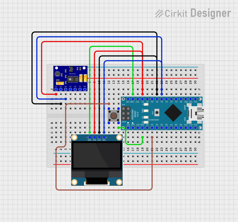
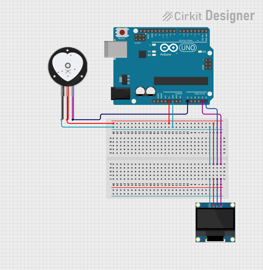
Interfacing with an Arduino UNO

  1. Connecting the Interface:

    • Connect the VCC pin to the 5V output on the Arduino.
    • Connect the GND pin to one of the GND pins on the Arduino.
    • Connect the DATA pin to a digital input pin on the Arduino (e.g., D2).
  2. Programming the Arduino:

    • Initialize the input pin with an interrupt to detect the heartbeats.
    • Use a timer to calculate the time between heartbeats and determine the heart rate.

Important Considerations and Best Practices

  • Ensure that the power supply voltage matches the operating voltage of the interface.
  • Use a pull-up resistor if the signal from the DATA pin is weak.
  • Avoid placing the interface near high-frequency or high-current devices to minimize noise.

Example Arduino Code

const int heartRatePin = 2; // Digital pin connected to the heart rate interface
volatile int heartBeatCounter = 0;
unsigned long lastHeartBeatTime = 0;

void setup() {
  Serial.begin(9600);
  pinMode(heartRatePin, INPUT);
  attachInterrupt(digitalPinToInterrupt(heartRatePin), heartBeatEvent, RISING);
}

void loop() {
  // Main loop does nothing; heart rate calculation is done in the interrupt.
}

// Interrupt service routine triggered on a heartbeat
void heartBeatEvent() {
  unsigned long currentTime = millis();
  // Calculate time between beats in milliseconds
  unsigned long beatInterval = currentTime - lastHeartBeatTime;
  lastHeartBeatTime = currentTime;
  
  // Increment the beat counter
  heartBeatCounter++;
  
  // Calculate heart rate in beats per minute (BPM)
  int heartRate = 60000 / beatInterval;
  
  // Output the heart rate to the serial monitor
  Serial.print("Heart Rate: ");
  Serial.print(heartRate);
  Serial.println(" BPM");
}

Troubleshooting and FAQs

Common Issues

  • No Data Output: Ensure that the sensor is properly connected and that the Polar heart rate sensor is functioning and in contact with the skin.
  • Inaccurate Readings: Check for loose connections and ensure that the sensor is worn correctly. Electromagnetic interference from nearby electronic devices can also cause inaccuracies.

Solutions and Tips for Troubleshooting

  • Verify that the power supply is stable and within the specified voltage range.
  • Ensure that the DATA pin is connected to the correct digital input on the Arduino.
  • Use a debounce algorithm or low-pass filter to smooth out the signal if there is too much noise.

FAQs

Q: Can the Polar Heart Rate Monitor Interface be used with other microcontrollers?

A: Yes, it can be used with any microcontroller that has digital input pins and can provide the appropriate voltage level.

Q: Is it necessary to use an external pull-up resistor?

A: It depends on the strength of the signal and the specific microcontroller's internal pull-up capabilities. An external pull-up resistor may be required if the signal is weak.

Q: How can I ensure the most accurate heart rate readings?

A: Ensure a good skin contact with the Polar heart rate sensor, minimize electromagnetic interference, and ensure a stable power supply to the interface.