How to Use ESP32 38 PINS: Examples, Pinouts, and Specs
Introduction
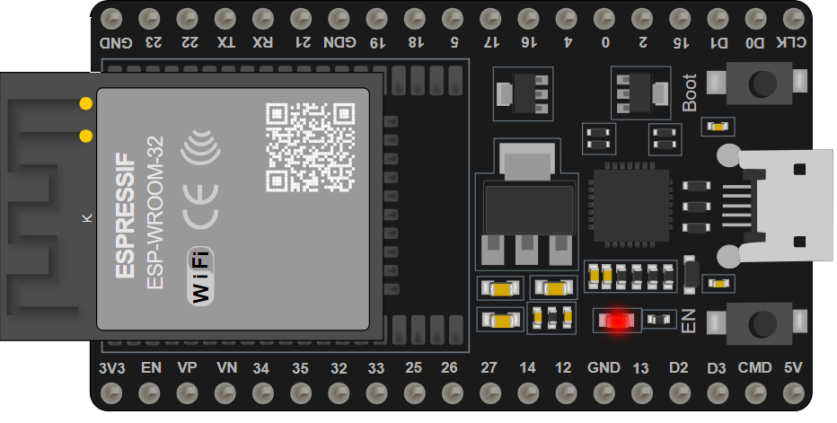
The ESP32 38 PINS is a versatile and powerful microcontroller board that comes equipped with both WiFi and Bluetooth capabilities. This board is an ideal choice for Internet of Things (IoT) projects, smart home applications, and various embedded systems that require wireless communication. With its 38 input/output pins, the ESP32 allows for extensive connectivity with a wide range of sensors, actuators, and peripherals, enabling developers to build complex and interactive projects.
Explore Projects Built with ESP32 38 PINS


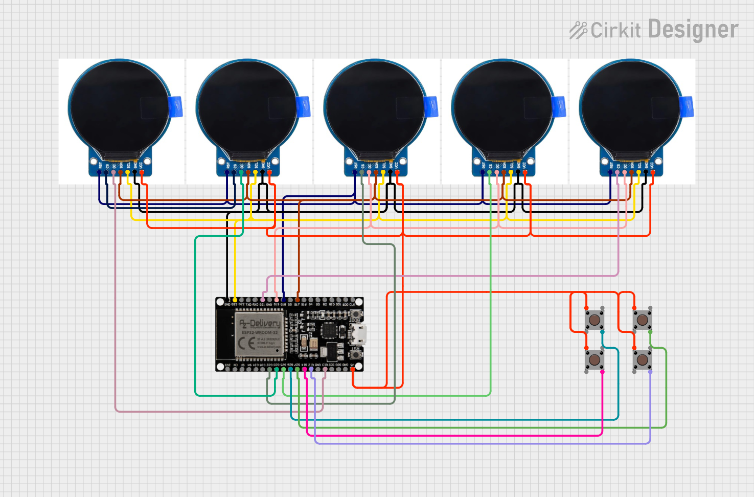

Explore Projects Built with ESP32 38 PINS
Technical Specifications
Key Technical Details
- Microcontroller: Tensilica LX6 dual-core processor
- Operating Voltage: 3.3V
- Input Voltage (recommended): 5V
- Input Voltage (limit): 6-12V
- Digital I/O Pins: 38
- Analog Input Pins: 18 (ADC channels)
- Analog Output Pins: 2 (DAC channels)
- Flash Memory: 4MB
- SRAM: 520 KB
- Clock Speed: 240 MHz
- Wi-Fi: 802.11 b/g/n
- Bluetooth: v4.2 BR/EDR and BLE
- Operating Temperature: -40°C to +125°C
Pin Configuration and Descriptions
| Pin Number | Function | Description |
|---|---|---|
| 1-22 | GPIO | General Purpose Input/Output pins |
| 23-36 | GPIO (with ADC) | GPIO pins with Analog-to-Digital Conversion |
| 37-38 | GPIO (with DAC) | GPIO pins with Digital-to-Analog Conversion |
| GND | Ground | Common ground for power and signal |
| 3V3 | 3.3V Power | 3.3V power supply pin |
| VIN | Voltage Input | Input voltage for the board (5V recommended) |
| EN | Enable | Chip enable, active high |
| TX0, RX0 | UART | Serial communication pins (UART0) |
| TX2, RX2 | UART | Serial communication pins (UART2) |
| SDA, SCL | I2C | I2C communication pins |
| MISO, MOSI, SCK, SS | SPI | SPI communication pins |
Usage Instructions
Integrating ESP32 into a Circuit
Powering the ESP32: Connect the VIN pin to a 5V power supply, and GND to the ground. Ensure that the power supply can deliver sufficient current for your application.
Programming the ESP32: Use a micro USB cable to connect the ESP32 to your computer. Install the necessary drivers and development environment to upload code to the board.
Connecting I/O Devices: Connect sensors, actuators, or peripherals to the GPIO pins. Make sure to configure the pins correctly in your code.
Wireless Communication: Utilize the onboard WiFi and Bluetooth for wireless communication. Ensure proper antenna placement for optimal signal strength.
Best Practices
- Always use a current limiting resistor with LEDs to prevent damage.
- Use decoupling capacitors close to the power pins to smooth out power supply noise.
- Avoid drawing more than 12 mA from any GPIO pin.
- Ensure that the total current drawn from the 3.3V pin does not exceed 500 mA.
Troubleshooting and FAQs
Common Issues
- ESP32 not powering on: Check the power supply and connections. Ensure that the input voltage is within the specified range.
- Cannot upload code: Verify that the correct drivers are installed, the USB cable is functioning, and the correct board is selected in the development environment.
- WiFi/Bluetooth not working: Ensure that the antenna is properly connected and not obstructed. Check your code for proper initialization of wireless modules.
Solutions and Tips
- If the ESP32 is unresponsive, try pressing the EN button to reset the board.
- For analog readings, calibrate the ADC for more accurate results.
- Use external power sources when connecting high-power devices to the ESP32.
Example Code for Arduino UNO
#include <WiFi.h>

// Replace with your network credentials
const char* ssid = "your_SSID";
const char* password = "your_PASSWORD";

void setup() {
  Serial.begin(115200);

  // Connect to Wi-Fi
  WiFi.begin(ssid, password);
  while (WiFi.status() != WL_CONNECTED) {
    delay(1000);
    Serial.println("Connecting to WiFi...");
  }

  Serial.println("Connected to WiFi");
}

void loop() {
  // Your code here
}
Remember to replace your_SSID and your_PASSWORD with your actual WiFi network credentials. This code initializes the WiFi module and connects the ESP32 to your local network. The serial monitor will display the connection status.
For further assistance, consult the ESP32 forums and the extensive online community for project-specific advice and support.