
How to Use FT2232D: Examples, Pinouts, and Specs
 Design with FT2232D in Cirkit Designer
Introduction
The FT2232D, manufactured by FTDI, is a dual-channel USB to serial converter chip. It provides a high-speed USB interface for communication with multiple serial devices. The chip supports a variety of protocols, including UART, I2C, SPI, and JTAG, making it a versatile solution for embedded systems, debugging, and data communication applications.
Explore Projects Built with FT2232D
 Open Project in Cirkit Designer
 Open Project in Cirkit Designer
 Open Project in Cirkit Designer
 Open Project in Cirkit Designer
Explore Projects Built with FT2232D
Open Project in Cirkit DesignerOpen Project in Cirkit DesignerOpen Project in Cirkit DesignerOpen Project in Cirkit DesignerCommon Applications and Use Cases
- USB to UART, I2C, or SPI bridge for embedded systems
- Debugging and programming microcontrollers or FPGAs
- USB-based JTAG interface for hardware testing
- Multi-channel serial communication in industrial or consumer devices
- Data logging and monitoring systems
Technical Specifications
Key Technical Details
- Manufacturer Part ID: FT2232D
- USB Interface: USB 2.0 Full-Speed (12 Mbps)
- Number of Channels: 2 independent serial channels
- Supported Protocols: UART, I2C, SPI, JTAG, and Bit-Bang modes
- Operating Voltage: 3.3V (core) and 5V (I/O, tolerant)
- Data Transfer Rate: Up to 3 Mbps (UART) per channel
- Package: LQFP-48
- Operating Temperature Range: -40°C to +85°C
- EEPROM Support: External EEPROM for configuration
- Driver Support: Windows, macOS, Linux
Pin Configuration and Descriptions
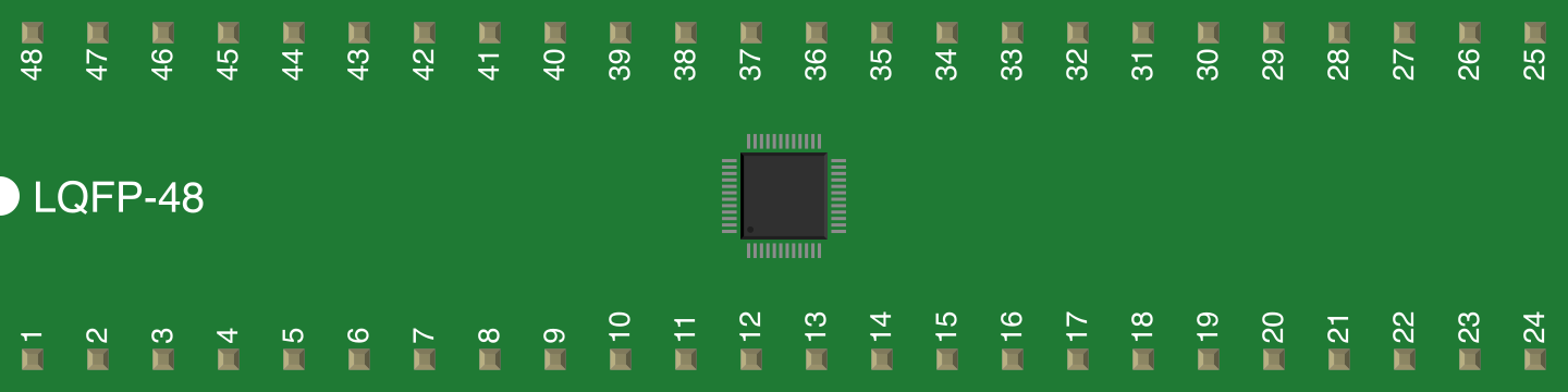
The FT2232D comes in a 48-pin LQFP package. Below is a summary of the key pins and their functions:
| Pin Number | Pin Name | Description |
|---|---|---|
| 1 | VCCIO | I/O Voltage Supply (3.3V or 5V tolerant) |
| 2 | TXD (A) | Transmit Data for Channel A |
| 3 | RXD (A) | Receive Data for Channel A |
| 4 | RTS# (A) | Request to Send for Channel A |
| 5 | CTS# (A) | Clear to Send for Channel A |
| 6 | TXD (B) | Transmit Data for Channel B |
| 7 | RXD (B) | Receive Data for Channel B |
| 8 | RTS# (B) | Request to Send for Channel B |
| 9 | CTS# (B) | Clear to Send for Channel B |
| 10 | GND | Ground |
| 11 | USB D+ | USB Data Positive |
| 12 | USB D- | USB Data Negative |
| 13 | RESET# | Active Low Reset Input |
| 14 | EEPROM | External EEPROM Interface |
| 15 | CLKOUT | Clock Output (12 MHz) |
| 16 | TEST | Test Pin (Leave unconnected in normal operation) |
| 17-48 | Other Pins | Various GPIOs, power, and configuration pins (refer to the FT2232D datasheet) |
Usage Instructions
How to Use the FT2232D in a Circuit
- Power Supply: Connect the VCCIO pin to a 3.3V or 5V power source, depending on the logic level of your system. Ensure proper decoupling capacitors are placed near the power pins.
- USB Connection: Connect the USB D+ and USB D- pins to a USB port using a USB cable. Include a 1.5kΩ pull-up resistor on the D+ line for USB compliance.
- Serial Communication: Use the TXD, RXD, RTS#, and CTS# pins for UART communication. For SPI or I2C, configure the chip using the appropriate driver or software.
- External EEPROM: If custom configurations are required, connect an external EEPROM to the EEPROM interface pins.
- Driver Installation: Install the FTDI-provided drivers on your host system. These drivers are available for Windows, macOS, and Linux.
Important Considerations and Best Practices
- Driver Configuration: Use the FTDI-provided Virtual COM Port (VCP) or Direct (D2XX) drivers for optimal performance.
- Signal Integrity: Keep USB and serial signal traces short and properly terminated to avoid noise and signal degradation.
- EEPROM Programming: Use FTDI's FT_PROG utility to program the external EEPROM for custom configurations.
- GPIO Usage: The FT2232D supports Bit-Bang mode, allowing GPIO pins to be controlled directly. Refer to the datasheet for details.
Example: Using FT2232D with Arduino UNO
The FT2232D can be used to communicate with an Arduino UNO via UART. Below is an example Arduino sketch for serial communication:
// Arduino UNO Serial Communication Example with FT2232D
// This sketch sends data to the FT2232D and receives data back.

void setup() {
  Serial.begin(9600); // Initialize UART at 9600 baud rate
  while (!Serial) {
    // Wait for the serial port to connect (for native USB boards)
  }
  Serial.println("FT2232D Communication Initialized");
}

void loop() {
  if (Serial.available()) {
    char received = Serial.read(); // Read data from FT2232D
    Serial.print("Received: ");
    Serial.println(received); // Echo received data back
  }
  delay(100); // Small delay for stability
}
Troubleshooting and FAQs
Common Issues and Solutions
Device Not Recognized by Host System:
- Ensure the USB cable is properly connected.
- Verify that the FTDI drivers are installed correctly.
- Check the USB D+ and D- connections for proper wiring.
No Data Transmission:
- Confirm that the TXD and RXD pins are correctly connected.
- Verify the baud rate and other serial settings match between devices.
- Check for proper power supply and grounding.
EEPROM Not Detected:
- Ensure the external EEPROM is connected correctly.
- Use FT_PROG to verify and program the EEPROM.
Signal Noise or Data Corruption:
- Use shorter signal traces and proper shielding.
- Add decoupling capacitors near the power pins.
FAQs
Q: Can the FT2232D operate at 5V logic levels?
- A: Yes, the FT2232D is 5V tolerant on its I/O pins, but the core operates at 3.3V.
Q: How do I switch between UART, SPI, and I2C modes?
- A: Use the FTDI-provided drivers or libraries to configure the desired protocol.
Q: Is the FT2232D compatible with Linux?
- A: Yes, FTDI provides Linux drivers for the FT2232D.
Q: Can I use the FT2232D for JTAG debugging?
- A: Yes, the FT2232D supports JTAG mode for debugging and programming.
For more detailed information, refer to the official FT2232D datasheet and application notes provided by FTDI.