How to Use IDC connector 2x8: Examples, Pinouts, and Specs
Introduction
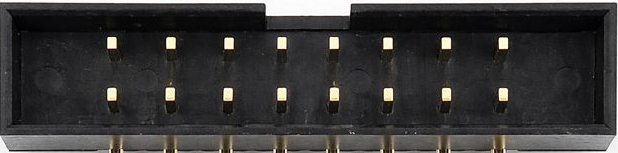
The IDC (Insulation Displacement Connector) 2x8 is a 16-pin connector arranged in two parallel rows of 8 pins each. It is designed for use with flat ribbon cables, allowing for quick and reliable connections to printed circuit boards (PCBs). The IDC connector is widely used in applications where compact, durable, and efficient connections are required, such as in computer systems, industrial equipment, and embedded systems.
Explore Projects Built with IDC connector 2x8


Explore Projects Built with IDC connector 2x8
Common Applications and Use Cases
- Connecting flat ribbon cables to PCBs in electronic devices
- Data transmission in computer peripherals and internal components
- Industrial control systems and automation
- Embedded systems and prototyping
- Signal and power distribution in compact electronic assemblies
Technical Specifications
The IDC Connector 2x8 is designed to meet the needs of modern electronic systems. Below are its key technical details:
Key Technical Details
- Number of Pins: 16 (2 rows of 8 pins)
- Pitch: 2.54 mm (0.1 inch) between adjacent pins
- Connector Type: Insulation Displacement Connector (IDC)
- Cable Compatibility: Flat ribbon cables with 1.27 mm (0.05 inch) pitch
- Current Rating: Typically 1A per pin (varies by manufacturer)
- Voltage Rating: Typically 250V (varies by manufacturer)
- Operating Temperature: -40°C to +105°C
- Material: Plastic housing with tin- or gold-plated contacts
Pin Configuration and Descriptions
The IDC Connector 2x8 has two rows of 8 pins, typically numbered as follows:
| Pin Number (Row 1) | Pin Number (Row 2) | Description |
|---|---|---|
| 1 | 2 | Signal or power connection |
| 3 | 4 | Signal or power connection |
| 5 | 6 | Signal or power connection |
| 7 | 8 | Signal or power connection |
| 9 | 10 | Signal or power connection |
| 11 | 12 | Signal or power connection |
| 13 | 14 | Signal or power connection |
| 15 | 16 | Signal or power connection |
Note: The specific pin assignments depend on the application and the device to which the connector is attached. Always refer to the corresponding circuit or device documentation for exact pin mappings.
Usage Instructions
How to Use the IDC Connector 2x8 in a Circuit
Prepare the Ribbon Cable:
- Use a flat ribbon cable with a 1.27 mm (0.05 inch) pitch.
- Cut the cable to the desired length and ensure the ends are clean and straight.
Attach the Connector:
- Align the ribbon cable with the IDC connector, ensuring proper orientation.
- Use an IDC crimping tool or a bench press to press the connector onto the cable. The insulation displacement mechanism will pierce the cable insulation and establish contact with the wires.
Connect to the PCB:
- Insert the IDC connector into the corresponding header on the PCB.
- Ensure the connector is fully seated and locked in place.
Verify Connections:
- Use a multimeter to check continuity between the ribbon cable and the PCB to ensure proper connections.
Important Considerations and Best Practices
- Cable Orientation: Ensure the ribbon cable is aligned correctly with the connector to avoid reversed connections.
- Strain Relief: Use strain relief clips or housings to prevent stress on the cable and connector.
- Pinout Verification: Double-check the pinout of the connector and the PCB header to avoid miswiring.
- Environmental Conditions: Ensure the connector is used within its rated temperature and voltage limits.
Example: Connecting to an Arduino UNO
The IDC Connector 2x8 can be used to connect a flat ribbon cable to an Arduino UNO via a custom shield or breakout board. Below is an example of how to read digital inputs from an IDC-connected device:
// Example: Reading digital inputs from an IDC-connected device
// Assumes the IDC connector is wired to Arduino digital pins 2-9

void setup() {
  // Initialize pins 2-9 as inputs
  for (int pin = 2; pin <= 9; pin++) {
    pinMode(pin, INPUT);
  }
  Serial.begin(9600); // Start serial communication
}

void loop() {
  // Read and print the state of each pin
  for (int pin = 2; pin <= 9; pin++) {
    int state = digitalRead(pin); // Read the pin state
    Serial.print("Pin ");
    Serial.print(pin);
    Serial.print(": ");
    Serial.println(state); // Print the state (HIGH or LOW)
  }
  delay(1000); // Wait 1 second before repeating
}
Note: Ensure the ribbon cable is correctly wired to the Arduino pins, and verify the pinout before powering the circuit.
Troubleshooting and FAQs
Common Issues and Solutions
Loose Connections:
- Issue: The IDC connector is not securely attached to the ribbon cable or PCB.
- Solution: Re-crimp the connector using an IDC crimping tool and ensure it is fully seated on the PCB header.
Incorrect Pinout:
- Issue: The device does not function as expected due to incorrect wiring.
- Solution: Verify the pinout of the connector and the PCB header. Use a multimeter to check continuity.
Damaged Cable or Connector:
- Issue: The ribbon cable or connector is physically damaged.
- Solution: Replace the damaged cable or connector and ensure proper handling during assembly.
Intermittent Connections:
- Issue: The connection is unreliable or intermittent.
- Solution: Check for loose or damaged pins, and ensure the connector is properly seated. Use strain relief to reduce stress on the cable.
FAQs
Q1: Can the IDC Connector 2x8 handle power connections?
A1: Yes, it can handle low-power connections (typically up to 1A per pin). For higher currents, use multiple pins in parallel or a dedicated power connector.
Q2: How do I ensure proper alignment when crimping the connector?
A2: Use an IDC crimping tool with alignment guides to ensure the ribbon cable is properly positioned before crimping.
Q3: Can I reuse an IDC connector?
A3: Reusing an IDC connector is not recommended, as the insulation displacement mechanism may not provide reliable connections after the first use.
Q4: What is the maximum cable length for an IDC connection?
A4: The maximum cable length depends on the application and signal type. For digital signals, shorter cables (less than 1 meter) are recommended to minimize signal degradation.