Cirkit Designer Logo
Cirkit Designer
Your all-in-one circuit design IDE
Home / 
Component Documentation

How to Use Adafruit ATtiny8x7 Breakout with seesaw: Examples, Pinouts, and Specs
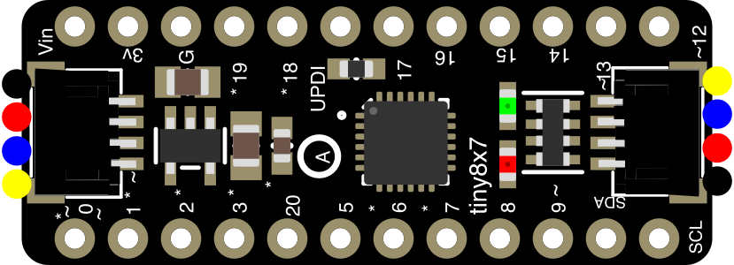

Image of Adafruit ATtiny8x7 Breakout with seesaw
Cirkit Designer LogoDesign with Adafruit ATtiny8x7 Breakout with seesaw in Cirkit Designer

Introduction

The Adafruit ATtiny8x7 Breakout with seesaw (Part ID: 5233) is a compact and versatile microcontroller board based on the ATtiny8x7 chip. It is designed to simplify I/O operations using Adafruit's seesaw library, which abstracts complex tasks like GPIO control, ADC, PWM, and more. This breakout board is ideal for projects requiring efficient control of sensors, LEDs, buttons, or other peripherals with minimal coding effort.

Explore Projects Built with Adafruit ATtiny8x7 Breakout with seesaw
Use Cirkit Designer to design, explore, and prototype these projects online. Some projects support real-time simulation. Click "Open Project" to start designing instantly!
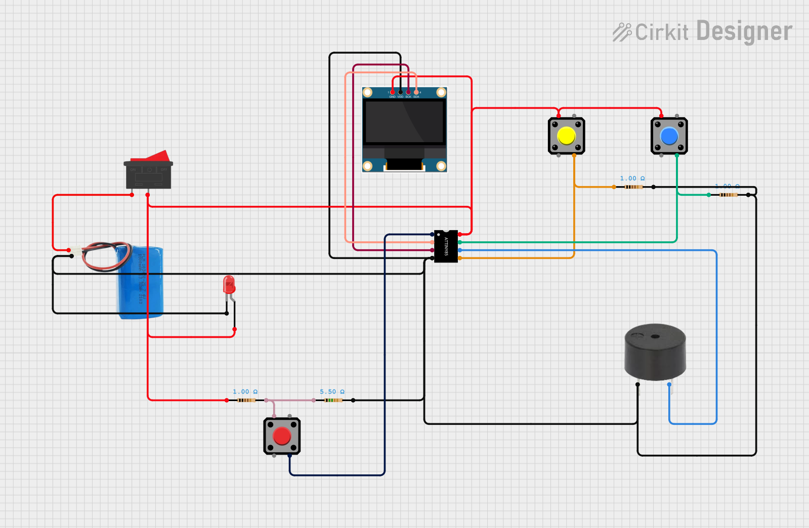
ATtiny85 and OLED Display Based Interactive Game with Buzzer and LED
Image of FIRST CIRCUIT: A project utilizing Adafruit ATtiny8x7 Breakout with seesaw in a practical application
This circuit is a simple interactive game system powered by a 5V battery, featuring an ATtiny85 microcontroller, an OLED display, a buzzer, an LED, and multiple pushbuttons. The OLED displays a menu with options to start a game, which is controlled by the ATtiny85. The buzzer and LED provide audio-visual feedback, and the pushbuttons are used for user input to navigate the menu and play the game.
Cirkit Designer LogoOpen Project in Cirkit Designer
ATmega328P-Based Sensor Hub with OLED Display and LIDAR
Image of TILTPCB: A project utilizing Adafruit ATtiny8x7 Breakout with seesaw in a practical application
This circuit features an Mtiny Uno ATmega328P microcontroller as its central processing unit, interfacing with a variety of sensors and peripherals. It includes a 0.96" OLED display and an MPU6050 accelerometer/gyroscope for user interface and motion sensing, respectively. The circuit also integrates a TF LUNA LIDAR for distance measurement, a DHT11 sensor for temperature and humidity readings, and uses a 9V battery with a 7805 voltage regulator for power management. Communication with a computer for programming and data exchange is facilitated by an Adafruit FTDI Friend module.
Cirkit Designer LogoOpen Project in Cirkit Designer
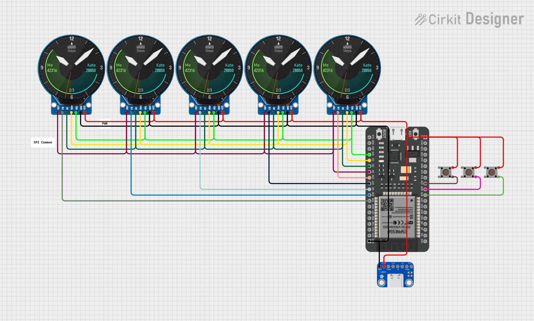
ESP32-Powered NTP Clock with Multiple GC9A01 Displays
Image of InfoOrbsFork: A project utilizing Adafruit ATtiny8x7 Breakout with seesaw in a practical application
This circuit features an ESP32 microcontroller connected to multiple GC9A01 displays and a USB Type C breakout for power. The ESP32 runs a sketch to retrieve the current time from an NTP server over WiFi and displays the hours and minutes across the GC9A01 displays, with each display showing a single digit or colon separator. Pushbuttons are connected to GPIOs on the ESP32, potentially for user input to control display functions or settings.
Cirkit Designer LogoOpen Project in Cirkit Designer
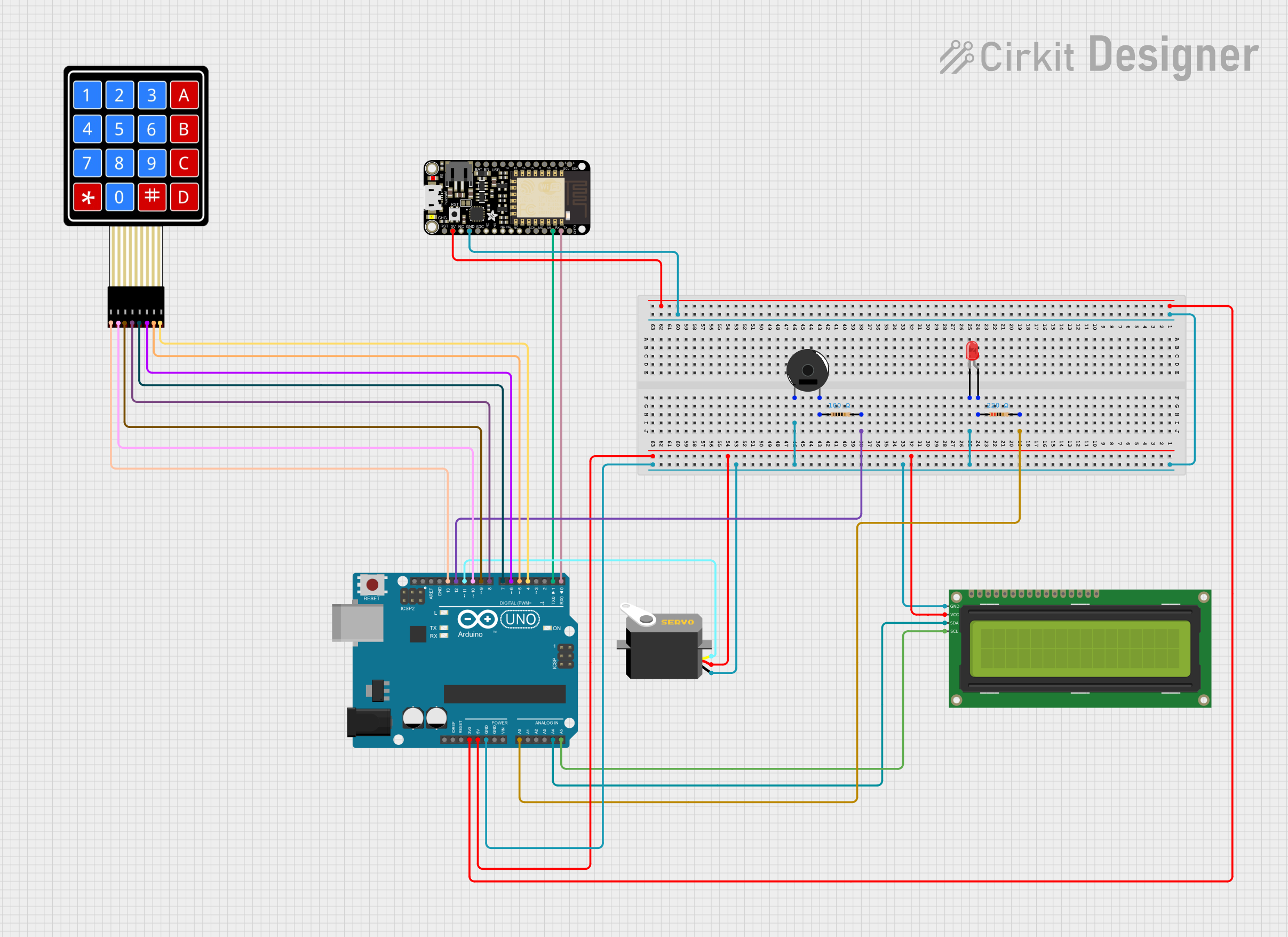
Arduino and ESP8266 Wi-Fi Interactive Control Panel
Image of Circuit schematic: A project utilizing Adafruit ATtiny8x7 Breakout with seesaw in a practical application
This circuit features an Arduino UNO and an Adafruit Feather HUZZAH ESP8266 microcontroller, which are interconnected for serial communication. The Arduino is also connected to a 16x2 I2C LCD for display, a servo motor, a piezo buzzer, an LED with a resistor, and a 4x4 membrane matrix keypad for user input. The purpose of the circuit is likely to involve user interaction through the keypad, feedback through the LCD, LED, and buzzer, and control of the servo motor, with potential WiFi capabilities provided by the ESP8266.
Cirkit Designer LogoOpen Project in Cirkit Designer

Explore Projects Built with Adafruit ATtiny8x7 Breakout with seesaw

Use Cirkit Designer to design, explore, and prototype these projects online. Some projects support real-time simulation. Click "Open Project" to start designing instantly!
Image of FIRST CIRCUIT: A project utilizing Adafruit ATtiny8x7 Breakout with seesaw in a practical application
ATtiny85 and OLED Display Based Interactive Game with Buzzer and LED
This circuit is a simple interactive game system powered by a 5V battery, featuring an ATtiny85 microcontroller, an OLED display, a buzzer, an LED, and multiple pushbuttons. The OLED displays a menu with options to start a game, which is controlled by the ATtiny85. The buzzer and LED provide audio-visual feedback, and the pushbuttons are used for user input to navigate the menu and play the game.
Cirkit Designer LogoOpen Project in Cirkit Designer
Image of TILTPCB: A project utilizing Adafruit ATtiny8x7 Breakout with seesaw in a practical application
ATmega328P-Based Sensor Hub with OLED Display and LIDAR
This circuit features an Mtiny Uno ATmega328P microcontroller as its central processing unit, interfacing with a variety of sensors and peripherals. It includes a 0.96" OLED display and an MPU6050 accelerometer/gyroscope for user interface and motion sensing, respectively. The circuit also integrates a TF LUNA LIDAR for distance measurement, a DHT11 sensor for temperature and humidity readings, and uses a 9V battery with a 7805 voltage regulator for power management. Communication with a computer for programming and data exchange is facilitated by an Adafruit FTDI Friend module.
Cirkit Designer LogoOpen Project in Cirkit Designer
Image of InfoOrbsFork: A project utilizing Adafruit ATtiny8x7 Breakout with seesaw in a practical application
ESP32-Powered NTP Clock with Multiple GC9A01 Displays
This circuit features an ESP32 microcontroller connected to multiple GC9A01 displays and a USB Type C breakout for power. The ESP32 runs a sketch to retrieve the current time from an NTP server over WiFi and displays the hours and minutes across the GC9A01 displays, with each display showing a single digit or colon separator. Pushbuttons are connected to GPIOs on the ESP32, potentially for user input to control display functions or settings.
Cirkit Designer LogoOpen Project in Cirkit Designer
Image of Circuit schematic: A project utilizing Adafruit ATtiny8x7 Breakout with seesaw in a practical application
Arduino and ESP8266 Wi-Fi Interactive Control Panel
This circuit features an Arduino UNO and an Adafruit Feather HUZZAH ESP8266 microcontroller, which are interconnected for serial communication. The Arduino is also connected to a 16x2 I2C LCD for display, a servo motor, a piezo buzzer, an LED with a resistor, and a 4x4 membrane matrix keypad for user input. The purpose of the circuit is likely to involve user interaction through the keypad, feedback through the LCD, LED, and buzzer, and control of the servo motor, with potential WiFi capabilities provided by the ESP8266.
Cirkit Designer LogoOpen Project in Cirkit Designer

Common Applications and Use Cases

  • Driving LEDs and controlling brightness using PWM
  • Reading analog sensors or potentiometers
  • Expanding GPIO capabilities for microcontrollers like Arduino or Raspberry Pi
  • Simplifying I2C-based communication for peripherals
  • Compact automation and control systems

Technical Specifications

The Adafruit ATtiny8x7 Breakout with seesaw is packed with features that make it a powerful yet easy-to-use component. Below are its key technical details:

Key Technical Details

  • Microcontroller: ATtiny817 (8-bit AVR microcontroller)
  • Operating Voltage: 3.3V (logic level)
  • Input Voltage Range: 3.3V to 5V (via onboard regulator)
  • Communication Protocol: I2C (default address: 0x49, configurable)
  • GPIO Pins: Up to 8 configurable pins
  • PWM Channels: 4 channels
  • ADC Channels: 4 channels (10-bit resolution)
  • Current Drive: Up to 20mA per GPIO pin
  • Dimensions: 25mm x 18mm x 2mm (excluding headers)

Pin Configuration and Descriptions

The breakout board features a simple pin layout for easy integration into your projects. Below is the pin configuration:

Pin Name Description
VIN Input voltage (3.3V to 5V). Powers the board via the onboard regulator.
GND Ground connection.
SCL I2C clock line. Connect to the SCL pin of your microcontroller.
SDA I2C data line. Connect to the SDA pin of your microcontroller.
GPIO 0-7 General-purpose I/O pins. Configurable as digital input/output, PWM, or ADC.
INT Interrupt pin. Can be used to signal events to the host microcontroller.
RST Reset pin. Pull low to reset the ATtiny8x7 chip.

Usage Instructions

The Adafruit ATtiny8x7 Breakout with seesaw is designed for ease of use. Follow the steps below to integrate it into your project:

Step 1: Wiring the Breakout Board

  1. Power the Board: Connect the VIN pin to a 3.3V or 5V power source and GND to ground.
  2. I2C Connection: Connect the SDA and SCL pins to the corresponding I2C pins on your microcontroller.
  3. Optional Connections: Use the GPIO pins for additional functionality like reading sensors or driving LEDs.

Step 2: Installing the seesaw Library

  1. Open the Arduino IDE.
  2. Go to Sketch > Include Library > Manage Libraries.
  3. Search for "Adafruit seesaw" and install the library.

Step 3: Example Code for Arduino UNO

Below is an example of how to use the breakout board to blink an LED connected to GPIO pin 0:

#include "Adafruit_seesaw.h"

// Create a seesaw object
Adafruit_seesaw ss;

void setup() {
  Serial.begin(115200);
  // Initialize the seesaw board
  if (!ss.begin(0x49)) { // Default I2C address is 0x49
    Serial.println("Seesaw not found! Check wiring.");
    while (1);
  }
  Serial.println("Seesaw initialized!");

  // Set GPIO pin 0 as an output
  ss.pinMode(0, OUTPUT);
}

void loop() {
  // Turn the LED on
  ss.digitalWrite(0, HIGH);
  delay(500); // Wait for 500ms

  // Turn the LED off
  ss.digitalWrite(0, LOW);
  delay(500); // Wait for 500ms
}

Important Considerations and Best Practices

  • Voltage Levels: Ensure your microcontroller operates at 3.3V logic levels or use a level shifter if operating at 5V.
  • I2C Address Conflicts: If multiple I2C devices are connected, ensure each has a unique address. The seesaw address can be changed in software.
  • GPIO Current Limits: Do not exceed 20mA per GPIO pin to avoid damaging the board.

Troubleshooting and FAQs

Common Issues and Solutions

  1. Seesaw Not Detected

    • Cause: Incorrect wiring or I2C address mismatch.
    • Solution: Verify SDA and SCL connections. Check the I2C address using an I2C scanner sketch.
  2. GPIO Pin Not Responding

    • Cause: Incorrect pin configuration.
    • Solution: Ensure the pin is configured as input or output using pinMode().
  3. Unstable Behavior

    • Cause: Insufficient power supply or noisy signals.
    • Solution: Use a decoupling capacitor (e.g., 0.1µF) near the VIN pin and ensure a stable power source.

Frequently Asked Questions

Q: Can I use this breakout board with a Raspberry Pi?
A: Yes, the board is compatible with Raspberry Pi. Use the I2C pins (SDA and SCL) on the Raspberry Pi GPIO header.

Q: How do I change the I2C address?
A: The I2C address can be changed in software using the seesaw library. Refer to the library documentation for details.

Q: Can I use all GPIO pins for PWM?
A: No, only 4 GPIO pins support PWM. Refer to the seesaw library documentation for pin-specific capabilities.

This concludes the documentation for the Adafruit ATtiny8x7 Breakout with seesaw. For further assistance, refer to the Adafruit product page or community forums.