Cirkit Designer Logo
Cirkit Designer
Your all-in-one circuit design IDE
Home / 
Component Documentation

How to Use current sensor: Examples, Pinouts, and Specs

Image of current sensor
Cirkit Designer LogoDesign with current sensor in Cirkit Designer

Introduction

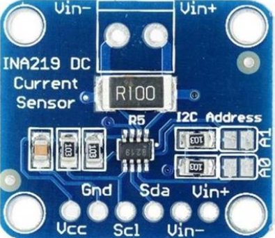
The INA219 is a high-side current shunt and power monitor with an I2C-compatible interface. Manufactured by Virgo Energy, the INA219 provides precise current and voltage monitoring with programmable calibration values. It is commonly used in applications such as battery chargers, power supplies, and portable instruments to monitor the current draw and power consumption of the system.

Explore Projects Built with current sensor

Use Cirkit Designer to design, explore, and prototype these projects online. Some projects support real-time simulation. Click "Open Project" to start designing instantly!
Wemos S2 Mini Controlled Smart Device with OLED Display, Thermal Printing, and RGB LED Strip
Image of DT NEA - Noah Patel: A project utilizing current sensor in a practical application
This circuit features a Wemos S2 Mini microcontroller that controls a WS2812 RGB LED strip and communicates with a 0.96" OLED display and a 58mm mini thermal printer. The ACS712 Current Sensor is interfaced with the microcontroller to monitor current, and power is managed by a CD42 BMS connected to two 18650 Li-ion batteries, with a USB-C PD Trigger Board for power delivery. The circuit is designed for visual output (LED strip, OLED display), printing capabilities, and current sensing, likely for a portable, battery-powered monitoring and display device.
Cirkit Designer LogoOpen Project in Cirkit Designer
ESP32-Based Current Monitoring and Temperature Sensing System
Image of SISTEMA DE MONITOREO: A project utilizing current sensor in a practical application
This circuit is designed to measure current using an ACS712 Current Sensor and temperature using a DS18B20 sensor, with an ESP32 microcontroller to process and possibly communicate the sensor data. The ACS712 sensor output is connected to one of the ESP32's analog input pins (D34), while the DS18B20's signal line is interfaced with a digital input pin (D23) through a pull-up resistor (4.7k Ohms). The ESP32 is powered through its Vin pin, and both sensors share a common ground with the ESP32.
Cirkit Designer LogoOpen Project in Cirkit Designer
Arduino UNO Based Ammeter with LCD Display
Image of ammeter: A project utilizing current sensor in a practical application
This circuit features an Arduino UNO microcontroller interfaced with an ACS712 current sensor and a 16x2 LCD screen using I2C communication. The Arduino reads the current value from the sensor and displays it on the LCD screen, also sending the data to the serial monitor. It is designed to function as an ammeter, measuring and displaying the current flowing through the sensor.
Cirkit Designer LogoOpen Project in Cirkit Designer
ESP32-Controlled Smart Lighting System with Power Monitoring
Image of Energy Monitoring System: A project utilizing current sensor in a practical application
This circuit appears to be a multi-channel current monitoring system using several ACS712 current sensors to measure the current through different loads, likely bulbs connected to a 220V power source. The current readings from the sensors are digitized by an Adafruit ADS1115 16-bit ADC, which interfaces with an ESP32 microcontroller via I2C communication for further processing or telemetry. A buck converter is used to step down the voltage to power the ESP32 and the sensors, and the system is powered through a 2.1mm DC barrel jack, indicating it is designed for external power supply.
Cirkit Designer LogoOpen Project in Cirkit Designer

Explore Projects Built with current sensor

Use Cirkit Designer to design, explore, and prototype these projects online. Some projects support real-time simulation. Click "Open Project" to start designing instantly!
Image of DT NEA - Noah Patel: A project utilizing current sensor in a practical application
Wemos S2 Mini Controlled Smart Device with OLED Display, Thermal Printing, and RGB LED Strip
This circuit features a Wemos S2 Mini microcontroller that controls a WS2812 RGB LED strip and communicates with a 0.96" OLED display and a 58mm mini thermal printer. The ACS712 Current Sensor is interfaced with the microcontroller to monitor current, and power is managed by a CD42 BMS connected to two 18650 Li-ion batteries, with a USB-C PD Trigger Board for power delivery. The circuit is designed for visual output (LED strip, OLED display), printing capabilities, and current sensing, likely for a portable, battery-powered monitoring and display device.
Cirkit Designer LogoOpen Project in Cirkit Designer
Image of SISTEMA DE MONITOREO: A project utilizing current sensor in a practical application
ESP32-Based Current Monitoring and Temperature Sensing System
This circuit is designed to measure current using an ACS712 Current Sensor and temperature using a DS18B20 sensor, with an ESP32 microcontroller to process and possibly communicate the sensor data. The ACS712 sensor output is connected to one of the ESP32's analog input pins (D34), while the DS18B20's signal line is interfaced with a digital input pin (D23) through a pull-up resistor (4.7k Ohms). The ESP32 is powered through its Vin pin, and both sensors share a common ground with the ESP32.
Cirkit Designer LogoOpen Project in Cirkit Designer
Image of ammeter: A project utilizing current sensor in a practical application
Arduino UNO Based Ammeter with LCD Display
This circuit features an Arduino UNO microcontroller interfaced with an ACS712 current sensor and a 16x2 LCD screen using I2C communication. The Arduino reads the current value from the sensor and displays it on the LCD screen, also sending the data to the serial monitor. It is designed to function as an ammeter, measuring and displaying the current flowing through the sensor.
Cirkit Designer LogoOpen Project in Cirkit Designer
Image of Energy Monitoring System: A project utilizing current sensor in a practical application
ESP32-Controlled Smart Lighting System with Power Monitoring
This circuit appears to be a multi-channel current monitoring system using several ACS712 current sensors to measure the current through different loads, likely bulbs connected to a 220V power source. The current readings from the sensors are digitized by an Adafruit ADS1115 16-bit ADC, which interfaces with an ESP32 microcontroller via I2C communication for further processing or telemetry. A buck converter is used to step down the voltage to power the ESP32 and the sensors, and the system is powered through a 2.1mm DC barrel jack, indicating it is designed for external power supply.
Cirkit Designer LogoOpen Project in Cirkit Designer

Technical Specifications

Key Technical Details

  • Voltage Range: 0 to 26V
  • Max Current: 3.2A (with default shunt resistor)
  • Resolution: 0.8mA (with default shunt resistor)
  • Communication: I2C interface
  • I2C Addresses: 0x40 to 0x4F (configurable with A0 and A1 pins)
  • Operating Temperature: -40°C to +85°C

Pin Configuration and Descriptions

Pin Number Name Description
1 V_IN+ Positive voltage input. Connect to the positive side of the power supply.
2 GND Ground. Connect to the system ground.
3 SDA I2C Data. Connect to the I2C data line.
4 SCL I2C Clock. Connect to the I2C clock line.
5 A0 Address pin 0. Used to set the I2C address.
6 A1 Address pin 1. Used to set the I2C address.
7 V_IN- Negative voltage input. Connect to the negative side of the shunt resistor.
8 V_BUS Bus voltage. Connect to the positive side of the shunt resistor.

Usage Instructions

How to Use the INA219 in a Circuit

  1. Connect the Power Supply: Connect the power supply's positive terminal to the V_IN+ pin and the negative terminal to the GND pin.
  2. Shunt Resistor: The INA219 comes with a built-in 0.1 ohm shunt resistor. Connect the load's positive terminal to the V_BUS pin and the negative terminal to the V_IN- pin.
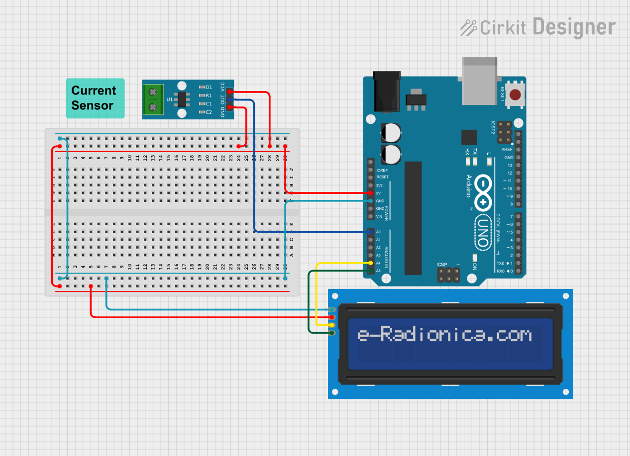
  3. I2C Communication: Connect the SDA and SCL pins to the corresponding I2C data and clock lines on your microcontroller, such as an Arduino UNO.
  4. Address Pins: Set the A0 and A1 pins to the desired logic levels to configure the I2C address if multiple devices are on the same bus.

Important Considerations and Best Practices

  • Ensure that the power supply voltage does not exceed the maximum rating of 26V.
  • Be cautious not to exceed the maximum current rating of 3.2A.
  • Use pull-up resistors on the I2C data and clock lines if they are not already present on the microcontroller board.
  • Place the INA219 as close as possible to the power source to minimize the effects of noise and resistance in the traces.

Example Code for Arduino UNO

#include <Wire.h>
#include <Adafruit_INA219.h>

Adafruit_INA219 ina219;

void setup() {
  Serial.begin(9600);
  while (!Serial) {
    // Wait for serial port to connect (needed for Leonardo only)
  }
  ina219.begin(); // Initialize the INA219
}

void loop() {
  float shuntvoltage = 0;
  float busvoltage = 0;
  float current_mA = 0;
  float loadvoltage = 0;

  busvoltage = ina219.getBusVoltage_V();
  shuntvoltage = ina219.getShuntVoltage_mV();
  current_mA = ina219.getCurrent_mA();
  loadvoltage = busvoltage + (shuntvoltage / 1000);
  
  Serial.print("Bus Voltage:   "); Serial.print(busvoltage); Serial.println(" V");
  Serial.print("Shunt Voltage: "); Serial.print(shuntvoltage); Serial.println(" mV");
  Serial.print("Load Voltage:  "); Serial.print(loadvoltage); Serial.println(" V");
  Serial.print("Current:       "); Serial.print(current_mA); Serial.println(" mA");
  Serial.println("");

  delay(2000);
}

Troubleshooting and FAQs

Common Issues

  • No Data on I2C: Check connections and pull-up resistors on the I2C lines.
  • Inaccurate Readings: Ensure proper calibration of the INA219. Follow the datasheet for calibration procedures.
  • Exceeding Current Limit: If the current exceeds 3.2A, consider using an external shunt resistor with a lower resistance value.

Solutions and Tips for Troubleshooting

  • Double-check wiring, especially the orientation of the INA219 and the connections to the power supply.
  • Use the I2C scanner sketch to confirm the device's address on the I2C bus.
  • Ensure that the INA219 library is correctly installed in your Arduino IDE.

FAQs

Q: Can I measure current in both directions? A: Yes, the INA219 can measure bidirectional current, but you may need to adjust the calibration settings.

Q: What is the maximum wire length for the I2C connection? A: I2C is typically used for short distances, but with proper shielding and pull-up resistors, longer distances up to a few meters can be achieved.

Q: How do I change the I2C address? A: The I2C address can be changed by setting the A0 and A1 pins to different logic levels. Refer to the datasheet for the address table.

Q: Can the INA219 be used with a microcontroller other than an Arduino? A: Yes, as long as the microcontroller supports I2C communication, you can use the INA219 with it. You may need to adapt the code and library accordingly.