How to Use AS5600: Examples, Pinouts, and Specs
Introduction
The AS5600 is a contactless magnetic rotary position sensor manufactured by C. It is designed to provide high-resolution angle measurements by detecting the position of a rotating magnet. This sensor is ideal for applications requiring precise angular position detection without physical contact, ensuring durability and reliability.
Explore Projects Built with AS5600


Explore Projects Built with AS5600
Common Applications and Use Cases
- Robotics: Joint and motor position sensing
- Automotive: Steering angle and throttle position detection
- Industrial automation: Rotary encoders and motor control
- Consumer electronics: Joysticks and knobs
- Medical devices: Position tracking in diagnostic equipment
Technical Specifications
The AS5600 offers a range of features that make it versatile and easy to integrate into various systems. Below are its key technical specifications:
| Parameter | Value |
|---|---|
| Supply Voltage (VDD) | 3.0V to 3.6V |
| Supply Current | 6.5 mA (typical) |
| Output Interfaces | Analog (PWM) and I²C |
| Resolution | 12-bit (4096 positions per revolution) |
| Operating Temperature Range | -40°C to +125°C |
| Magnetic Field Strength | 20 mT to 80 mT |
| Maximum Rotational Speed | 30,000 RPM |
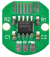
Pin Configuration and Descriptions
The AS5600 is typically available in an 8-pin SOIC package. Below is the pinout and description:
| Pin Number | Pin Name | Description |
|---|---|---|
| 1 | VDD | Power supply input (3.0V to 3.6V) |
| 2 | OUT | Analog output (PWM signal or voltage proportional to angle) |
| 3 | GND | Ground connection |
| 4 | SDA | I²C data line |
| 5 | SCL | I²C clock line |
| 6 | DIR | Direction input (sets clockwise or counterclockwise rotation) |
| 7 | MODE | Mode selection (configures output as analog or PWM) |
| 8 | NC | Not connected (leave floating or connect to GND for stability) |
Usage Instructions
The AS5600 is straightforward to use in a circuit, whether for analog or digital applications. Below are the steps and considerations for integrating the sensor:
Connecting the AS5600
- Power Supply: Connect the VDD pin to a 3.3V power source and the GND pin to ground.
- Output Mode: Use the MODE pin to select the desired output:
- Connect MODE to GND for analog output.
- Connect MODE to VDD for PWM output.
- Direction Control: Use the DIR pin to set the rotation direction:
- Connect DIR to GND for clockwise rotation.
- Connect DIR to VDD for counterclockwise rotation.
- I²C Communication: If using I²C, connect the SDA and SCL pins to the corresponding lines on your microcontroller. Pull-up resistors (typically 4.7kΩ) are required on both lines.
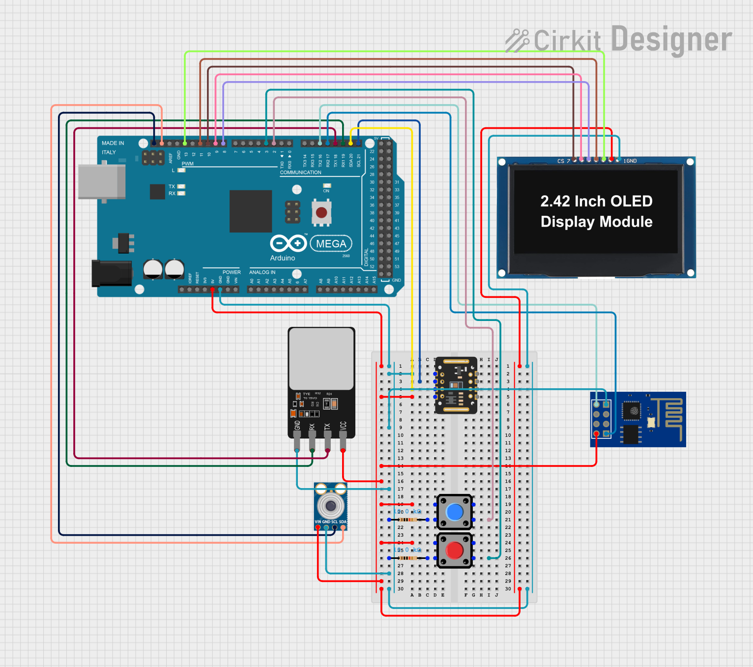
Example: Using AS5600 with Arduino UNO
The AS5600 can be easily interfaced with an Arduino UNO via I²C. Below is an example code snippet to read the angle:
#include <Wire.h>

// AS5600 I2C address
#define AS5600_ADDR 0x36

// Register addresses for angle data
#define AS5600_RAW_ANGLE_HIGH 0x0C
#define AS5600_RAW_ANGLE_LOW  0x0D

void setup() {
  Wire.begin(); // Initialize I2C communication
  Serial.begin(9600); // Start serial communication for debugging
}

void loop() {
  uint16_t rawAngle = readRawAngle(); // Read the raw angle value
  float angle = (rawAngle * 360.0) / 4096.0; // Convert to degrees (12-bit resolution)

  Serial.print("Angle: ");
  Serial.print(angle);
  Serial.println(" degrees");

  delay(500); // Wait for 500ms before the next reading
}

// Function to read the raw angle from AS5600
uint16_t readRawAngle() {
  Wire.beginTransmission(AS5600_ADDR); // Start communication with AS5600
  Wire.write(AS5600_RAW_ANGLE_HIGH);  // Request high byte of raw angle
  Wire.endTransmission(false);        // Send repeated start condition
  Wire.requestFrom(AS5600_ADDR, 2);   // Request 2 bytes (high and low)

  uint8_t highByte = Wire.read();     // Read high byte
  uint8_t lowByte = Wire.read();      // Read low byte

  return (highByte << 8) | lowByte;   // Combine high and low bytes
}
Important Considerations
- Magnet Selection: Use a diametrically magnetized magnet with a field strength between 20 mT and 80 mT for optimal performance.
- Placement: Ensure the magnet is centered and positioned 0.5mm to 3mm above the sensor for accurate readings.
- Noise Filtering: Use decoupling capacitors (e.g., 100nF) near the VDD pin to reduce noise.
- I²C Pull-Up Resistors: Ensure proper pull-up resistors are used on the SDA and SCL lines for reliable communication.
Troubleshooting and FAQs
Common Issues and Solutions
No Output Signal
- Cause: Incorrect power supply or loose connections.
- Solution: Verify that VDD is connected to a 3.3V source and all connections are secure.
Inaccurate Angle Measurements
- Cause: Magnet misalignment or incorrect placement.
- Solution: Ensure the magnet is centered and within the recommended distance from the sensor.
I²C Communication Failure
- Cause: Missing pull-up resistors or incorrect I²C address.
- Solution: Add 4.7kΩ pull-up resistors to SDA and SCL lines and confirm the AS5600 address (default: 0x36).
Output Signal is Noisy
- Cause: Power supply noise or insufficient decoupling.
- Solution: Add a 100nF capacitor near the VDD pin to filter noise.
FAQs
Q: Can the AS5600 measure angles beyond 360°?
A: No, the AS5600 measures angles within a single 360° rotation. For multiple rotations, additional logic is required to track revolutions.
Q: What happens if the magnetic field strength is too low or too high?
A: The AS5600 may produce inaccurate readings or fail to detect the magnet. Ensure the field strength is within the 20 mT to 80 mT range.
Q: Can I use the AS5600 with a 5V microcontroller?
A: Yes, but you must use a level shifter for the I²C lines or ensure the microcontroller's I²C pins are 3.3V tolerant.
Q: Is the AS5600 suitable for high-speed applications?
A: Yes, the AS5600 supports rotational speeds up to 30,000 RPM, making it suitable for high-speed applications.