How to Use Esp32-Wroom-32 Type C: Examples, Pinouts, and Specs
Introduction
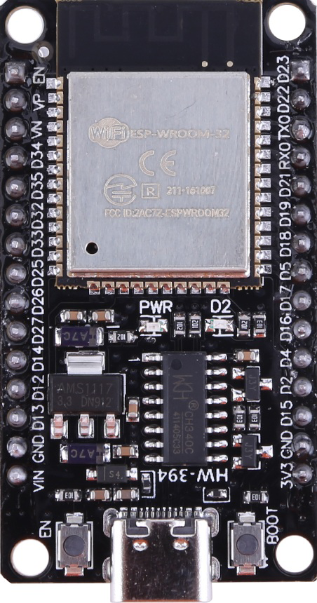
The ESP32-WROOM-32 Type C is a powerful and versatile Wi-Fi and Bluetooth module designed for IoT (Internet of Things) applications. It is based on the ESP32 microcontroller, which features a dual-core processor, integrated Wi-Fi, Bluetooth, and a wide range of peripherals. The Type C variant of the ESP32-WROOM-32 module is optimized for compact designs and offers excellent performance in a small form factor.
Explore Projects Built with Esp32-Wroom-32 Type C


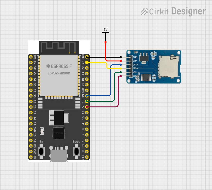
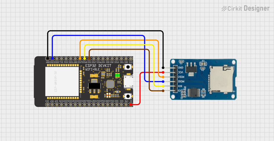
Explore Projects Built with Esp32-Wroom-32 Type C
Common Applications and Use Cases
- IoT devices and smart home automation
- Wearable electronics
- Wireless sensor networks
- Industrial automation
- Prototyping and development of connected devices
Technical Specifications
Key Technical Details
| Parameter | Value |
|---|---|
| Microcontroller | ESP32 dual-core Xtensa LX6 |
| Clock Speed | Up to 240 MHz |
| Flash Memory | 4 MB (default, may vary by model) |
| SRAM | 520 KB |
| Wireless Connectivity | Wi-Fi 802.11 b/g/n, Bluetooth v4.2 BR/EDR |
| Operating Voltage | 3.0V to 3.6V |
| GPIO Pins | 34 (multiplexed with other functions) |
| Communication Interfaces | UART, SPI, I2C, I2S, CAN, PWM, ADC, DAC |
| ADC Resolution | 12-bit |
| DAC Resolution | 8-bit |
| Operating Temperature | -40°C to 85°C |
| Dimensions | 18 mm x 25.5 mm |
Pin Configuration and Descriptions
| Pin Number | Pin Name | Function |
|---|---|---|
| 1 | EN | Enable pin (active high) |
| 2 | IO0 | GPIO0, used for boot mode selection |
| 3 | IO1 (TXD0) | UART0 TX, GPIO1 |
| 4 | IO3 (RXD0) | UART0 RX, GPIO3 |
| 5 | IO4 | GPIO4, PWM, ADC |
| 6 | IO5 | GPIO5, PWM, ADC |
| 7 | GND | Ground |
| 8 | 3V3 | 3.3V power supply input |
| 9 | IO12 | GPIO12, ADC, touch sensor |
| 10 | IO13 | GPIO13, ADC, touch sensor |
| ... | ... | ... (Refer to the full datasheet for all pins) |
Usage Instructions
How to Use the ESP32-WROOM-32 Type C in a Circuit
- Power Supply: Ensure the module is powered with a stable 3.3V supply. Avoid exceeding 3.6V to prevent damage.
- Boot Mode: To upload code, connect GPIO0 to GND and reset the module. After uploading, disconnect GPIO0 from GND.
- Connections: Use UART pins (TXD0 and RXD0) for serial communication with a computer or microcontroller. Connect GND to the ground of the circuit.
- Programming: The ESP32-WROOM-32 Type C can be programmed using the Arduino IDE or ESP-IDF (Espressif IoT Development Framework).
Important Considerations and Best Practices
- Use a level shifter if interfacing with 5V logic devices, as the ESP32 operates at 3.3V logic levels.
- Decouple the power supply with capacitors (e.g., 10 µF and 0.1 µF) close to the module to reduce noise.
- Avoid using GPIO pins that are reserved for internal functions (e.g., GPIO6 to GPIO11 are used for flash memory).
Example Code for Arduino UNO
Below is an example of how to blink an LED connected to GPIO2 of the ESP32-WROOM-32 Type C using the Arduino IDE:
// Include the Arduino core for ESP32
#include <Arduino.h>

// Define the GPIO pin for the LED
#define LED_PIN 2

void setup() {
  // Initialize the LED pin as an output
  pinMode(LED_PIN, OUTPUT);
}

void loop() {
  // Turn the LED on
  digitalWrite(LED_PIN, HIGH);
  delay(1000); // Wait for 1 second

  // Turn the LED off
  digitalWrite(LED_PIN, LOW);
  delay(1000); // Wait for 1 second
}
Troubleshooting and FAQs
Common Issues and Solutions
Module Not Responding:
- Ensure the module is powered correctly (3.3V supply).
- Check the connections, especially the UART TX and RX pins.
- Verify that GPIO0 is connected to GND during programming.
Wi-Fi Connection Fails:
- Double-check the SSID and password in your code.
- Ensure the Wi-Fi network is within range and not overloaded.
Code Upload Fails:
- Confirm that the correct COM port and board type are selected in the Arduino IDE.
- Press and hold the EN (reset) button while uploading the code.
FAQs
Q: Can the ESP32-WROOM-32 Type C operate on 5V?
A: No, the module operates at 3.3V. Use a voltage regulator or level shifter for 5V systems.
Q: How many devices can connect to the ESP32 via Bluetooth?
A: The ESP32 supports up to 7 simultaneous Bluetooth connections in classic mode.
Q: Can I use the ESP32-WROOM-32 Type C for battery-powered applications?
A: Yes, the module is suitable for battery-powered designs. Use deep sleep mode to minimize power consumption.
Q: What is the maximum Wi-Fi range of the ESP32?
A: The range depends on the environment but typically extends up to 100 meters in open spaces.