
How to Use nRF52840 ProMicro: Examples, Pinouts, and Specs
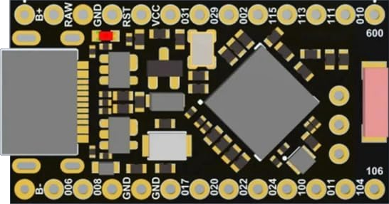
 Design with nRF52840 ProMicro in Cirkit Designer
Introduction
The nRF52840 ProMicro is a compact development board designed by Nordic Semiconductor, featuring the powerful nRF52840 SoC. This board integrates a 32-bit ARM Cortex-M4 processor with floating-point support, Bluetooth 5.0, and multi-protocol wireless communication capabilities. It is optimized for low-power applications, making it an excellent choice for IoT projects, wearable devices, and smart home applications. The board also includes USB connectivity, multiple GPIO pins, and a variety of peripherals to support versatile development needs.
Explore Projects Built with nRF52840 ProMicro
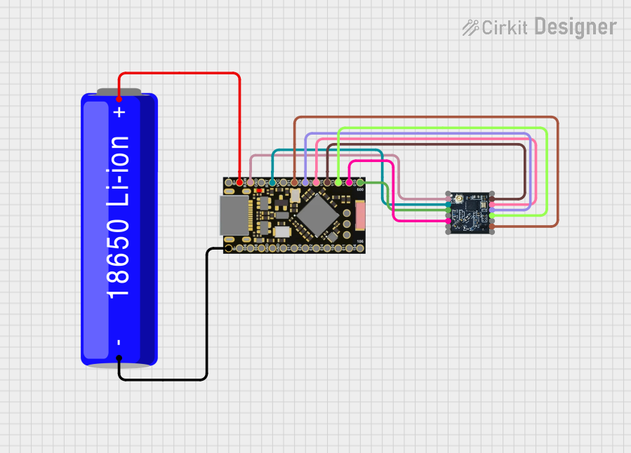 Open Project in Cirkit Designer
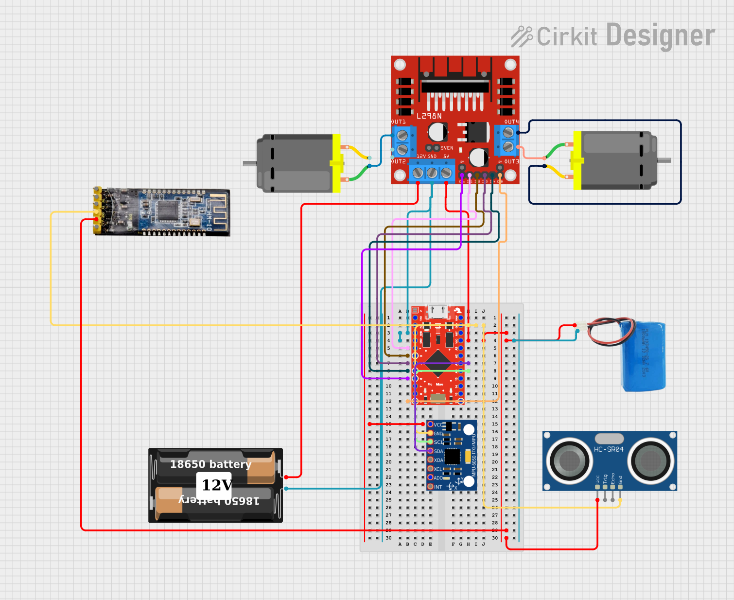 Open Project in Cirkit Designer
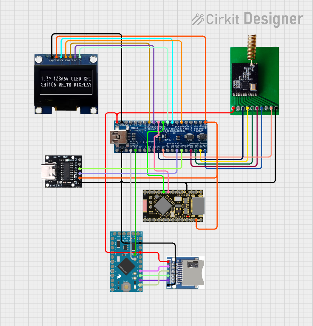 Open Project in Cirkit Designer
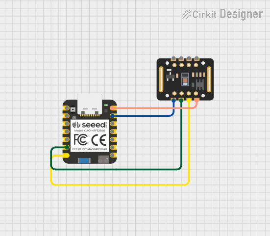 Open Project in Cirkit Designer
Explore Projects Built with nRF52840 ProMicro
Open Project in Cirkit DesignerOpen Project in Cirkit DesignerOpen Project in Cirkit DesignerOpen Project in Cirkit DesignerCommon Applications
- Internet of Things (IoT) devices
- Wearable technology
- Smart home automation
- Wireless sensors and beacons
- Low-power Bluetooth applications
- USB-enabled devices
Technical Specifications
Key Technical Details
| Parameter | Value |
|---|---|
| Processor | 32-bit ARM Cortex-M4 with FPU, running at 64 MHz |
| Wireless Protocols | Bluetooth 5.0, Bluetooth Mesh, Thread, Zigbee, 802.15.4, ANT, 2.4 GHz |
| Flash Memory | 1 MB |
| RAM | 256 KB |
| Operating Voltage | 1.7V to 3.6V |
| GPIO Pins | 21 (configurable as digital I/O, PWM, or analog inputs) |
| USB Support | Full-speed USB 2.0 |
| Communication Interfaces | I2C, SPI, UART, PDM, PWM, QSPI, NFC |
| Power Consumption | Ultra-low power consumption (down to 0.3 µA in sleep mode) |
| Dimensions | 33 mm x 18 mm |
Pin Configuration and Descriptions
The nRF52840 ProMicro features a total of 24 pins, including power, GPIO, and communication pins. Below is the pinout description:
| Pin Number | Pin Name | Description |
|---|---|---|
| 1 | VCC | Power input (1.7V to 3.6V) |
| 2 | GND | Ground |
| 3 | D0/RX | Digital I/O or UART RX |
| 4 | D1/TX | Digital I/O or UART TX |
| 5 | D2 | Digital I/O or PWM |
| 6 | D3 | Digital I/O or PWM |
| 7 | D4 | Digital I/O |
| 8 | D5 | Digital I/O or PWM |
| 9 | D6 | Digital I/O or PWM |
| 10 | D7 | Digital I/O |
| 11 | D8 | Digital I/O |
| 12 | D9 | Digital I/O or PWM |
| 13 | D10 | Digital I/O or PWM |
| 14 | D11 | Digital I/O or SPI MOSI |
| 15 | D12 | Digital I/O or SPI MISO |
| 16 | D13 | Digital I/O or SPI SCK |
| 17 | A0 | Analog input or Digital I/O |
| 18 | A1 | Analog input or Digital I/O |
| 19 | A2 | Analog input or Digital I/O |
| 20 | A3 | Analog input or Digital I/O |
| 21 | A4/SDA | Analog input, Digital I/O, or I2C SDA |
| 22 | A5/SCL | Analog input, Digital I/O, or I2C SCL |
| 23 | USB+ | USB D+ line |
| 24 | USB- | USB D- line |
Usage Instructions
How to Use the nRF52840 ProMicro in a Circuit
Powering the Board:
- Connect the VCC pin to a power source within the range of 1.7V to 3.6V.
- Ensure the GND pin is connected to the ground of your circuit.
Programming the Board:
- Use a USB cable to connect the board to your computer.
- The board supports programming via the Arduino IDE or Nordic's nRF Connect SDK.
Connecting Peripherals:
- Use the GPIO pins for digital I/O, PWM, or analog input as required.
- For communication, connect peripherals to the I2C, SPI, or UART pins.
Wireless Communication:
- Configure the Bluetooth or other wireless protocols using Nordic's SDK or Arduino libraries.
Important Considerations
- Voltage Levels: Ensure all connected peripherals operate within the board's voltage range (1.7V to 3.6V).
- Power Consumption: Utilize the board's low-power modes for battery-powered applications.
- Antenna Placement: Avoid placing metal objects near the onboard antenna to ensure optimal wireless performance.
- Firmware Updates: Regularly update the firmware using Nordic's tools to access the latest features and bug fixes.
Example Code for Arduino UNO Integration
Below is an example of using the nRF52840 ProMicro with the Arduino IDE to blink an LED connected to pin D13:
// Example: Blink an LED on pin D13 of the nRF52840 ProMicro

// Define the LED pin
const int ledPin = 13;

void setup() {
  // Initialize the LED pin as an output
  pinMode(ledPin, OUTPUT);
}

void loop() {
  // Turn the LED on
  digitalWrite(ledPin, HIGH);
  delay(1000); // Wait for 1 second

  // Turn the LED off
  digitalWrite(ledPin, LOW);
  delay(1000); // Wait for 1 second
}
Troubleshooting and FAQs
Common Issues and Solutions
The board is not detected by the computer:
- Ensure the USB cable is properly connected and functional.
- Check if the board is in bootloader mode by double-tapping the reset button.
Wireless communication is not working:
- Verify that the correct wireless protocol is enabled in the firmware.
- Ensure there are no obstructions or interference near the antenna.
Power issues:
- Confirm that the input voltage is within the specified range (1.7V to 3.6V).
- Check for loose connections or damaged components.
Programming errors in the Arduino IDE:
- Install the necessary board definitions and libraries for the nRF52840 ProMicro.
- Ensure the correct COM port and board type are selected in the IDE.
FAQs
Q: Can I use the nRF52840 ProMicro for Bluetooth Mesh applications?
A: Yes, the board supports Bluetooth Mesh, as well as other wireless protocols like Thread and Zigbee.
Q: What is the maximum range of the Bluetooth connection?
A: The range depends on environmental factors but can reach up to 100 meters in open spaces.
Q: Does the board support battery-powered operation?
A: Yes, the board is optimized for low-power applications and can be powered by batteries.
Q: Can I use the board with Nordic's nRF Connect SDK?
A: Absolutely. The board is fully compatible with Nordic's nRF Connect SDK for advanced development.
This concludes the documentation for the nRF52840 ProMicro. For further assistance, refer to Nordic Semiconductor's official resources or community forums.