How to Use class d: Examples, Pinouts, and Specs
Introduction
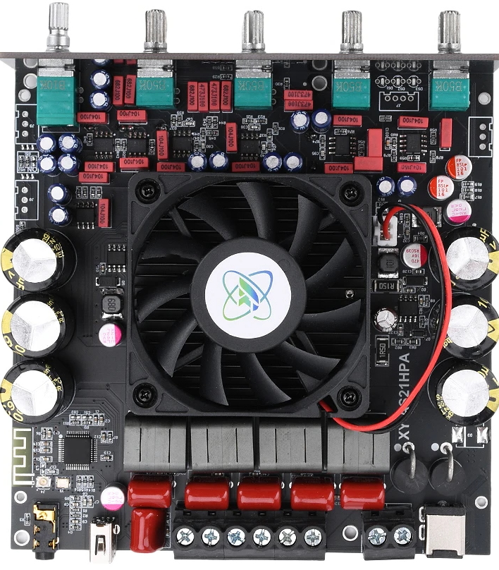
A Class D amplifier is a highly efficient audio amplifier that operates using pulse-width modulation (PWM) to amplify audio signals. Unlike traditional linear amplifiers, Class D amplifiers convert the input audio signal into a series of high-frequency pulses, which are then amplified and filtered to reconstruct the audio signal at the output. This design allows for efficiency levels often exceeding 90%, making it ideal for applications where power consumption and heat dissipation are critical.
Explore Projects Built with class d
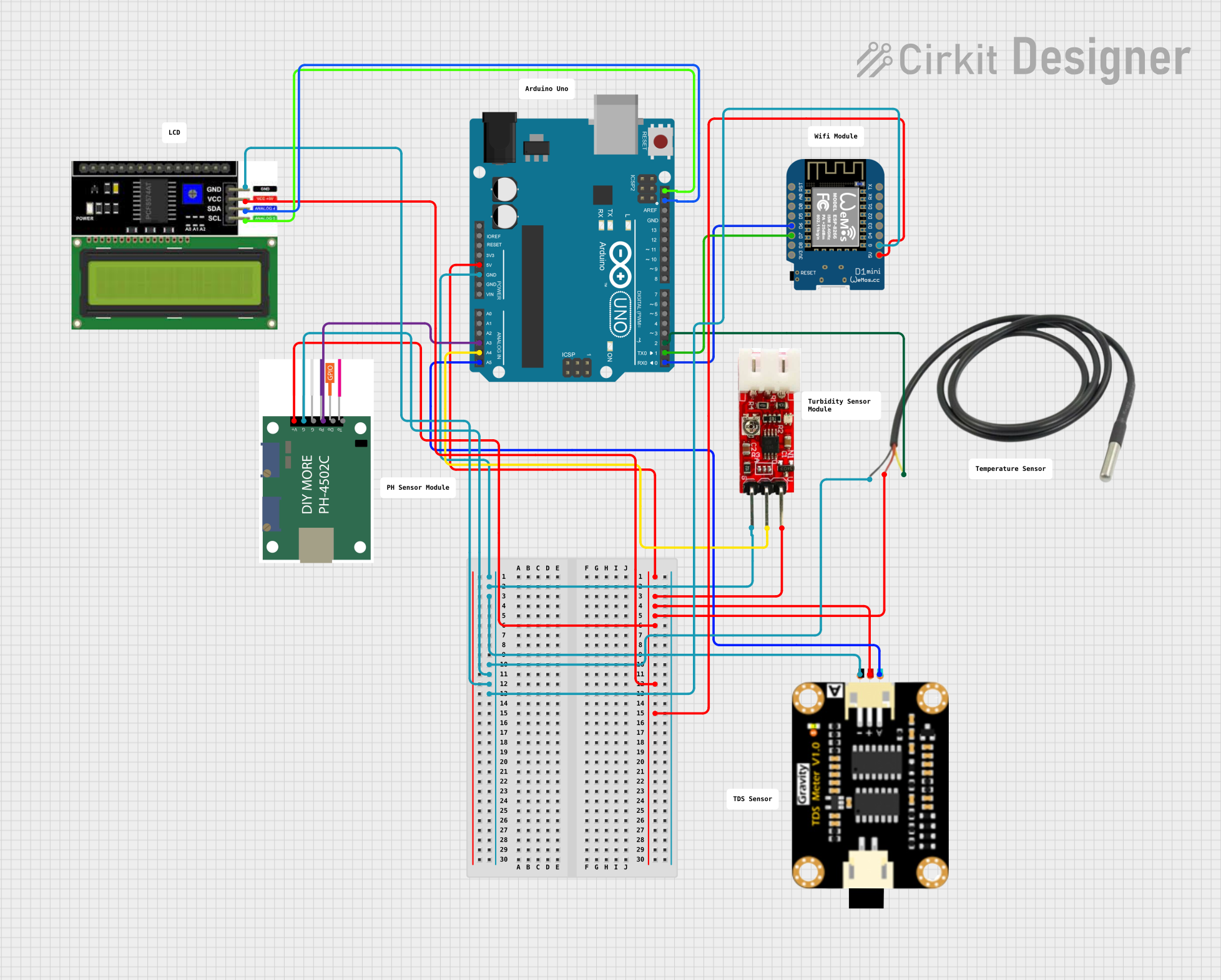
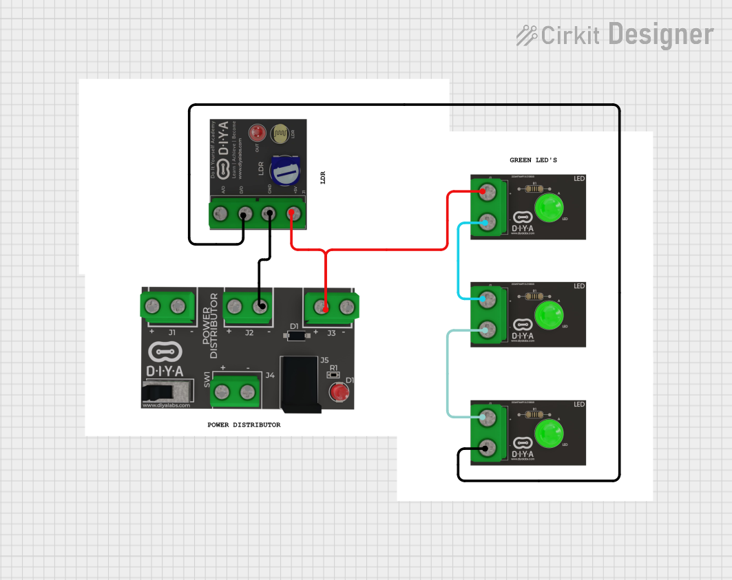


Explore Projects Built with class d
Common Applications and Use Cases
- Portable audio devices: Bluetooth speakers, headphones, and portable amplifiers.
- Home audio systems: High-power sound systems and subwoofers.
- Automotive audio: Car stereo systems and amplifiers.
- Industrial and commercial audio: Public address systems and sound reinforcement.
- Battery-powered devices: Devices requiring long battery life and minimal heat generation.
Technical Specifications
Below are the general technical specifications for a typical Class D amplifier. Specific values may vary depending on the manufacturer and model.
| Parameter | Value |
|---|---|
| Manufacturer | Class D |
| Manufacturer Part ID | Class D |
| Amplifier Type | Class D (PWM-based) |
| Efficiency | >90% |
| Output Power | 10W to 1000W (varies by model) |
| Supply Voltage Range | 5V to 48V (depending on design) |
| Frequency Response | 20 Hz to 20 kHz (audio range) |
| Total Harmonic Distortion (THD) | <0.1% |
| Signal-to-Noise Ratio (SNR) | >90 dB |
| Input Impedance | 10 kΩ to 100 kΩ |
| Output Impedance | Typically 4Ω or 8Ω |
Pin Configuration and Descriptions
The pin configuration for a typical Class D amplifier IC is shown below. Note that the exact pinout may vary depending on the specific IC used.
| Pin Name | Description |
|---|---|
| VCC | Positive power supply input |
| GND | Ground connection |
| IN+ | Non-inverting audio input |
| IN- | Inverting audio input |
| OUT+ | Positive speaker output |
| OUT- | Negative speaker output |
| SHDN | Shutdown control (active low) |
| NC | No connection (leave unconnected) |
Usage Instructions
How to Use the Component in a Circuit
- Power Supply: Ensure the power supply voltage matches the amplifier's specifications. For example, if the amplifier operates at 12V, use a regulated 12V DC power source.
- Input Signal: Connect the audio source (e.g., a smartphone or audio player) to the IN+ and IN- pins. Use a coupling capacitor if required to block DC offset.
- Speaker Connection: Connect the speaker to the OUT+ and OUT- pins. Ensure the speaker impedance matches the amplifier's output impedance (e.g., 4Ω or 8Ω).
- Shutdown Control: If the amplifier has a shutdown pin (SHDN), connect it to GND to disable the amplifier or leave it floating/high to enable it.
- Decoupling Capacitors: Place decoupling capacitors (e.g., 0.1 µF and 10 µF) close to the VCC and GND pins to reduce noise and stabilize the power supply.
Important Considerations and Best Practices
- Heat Dissipation: Although Class D amplifiers are highly efficient, high-power models may still require heat sinks or proper ventilation.
- Filtering: Use appropriate LC filters at the output to remove high-frequency switching noise and ensure clean audio output.
- PCB Layout: Minimize the length of high-current traces and use proper grounding techniques to reduce electromagnetic interference (EMI).
- Speaker Protection: Avoid connecting speakers with impedance lower than the amplifier's rated output impedance to prevent damage.
Example: Using a Class D Amplifier with Arduino UNO
Below is an example of how to control a Class D amplifier using an Arduino UNO to generate a PWM signal.
// Example: Generating a PWM signal for a Class D amplifier
// Connect the amplifier's IN+ pin to Arduino pin 9
// Connect the amplifier's IN- pin to GND

void setup() {
  pinMode(9, OUTPUT); // Set pin 9 as an output
}

void loop() {
  analogWrite(9, 128); // Generate a 50% duty cycle PWM signal
  delay(1000);         // Wait for 1 second
  analogWrite(9, 255); // Generate a 100% duty cycle PWM signal
  delay(1000);         // Wait for 1 second
}
Note: The above code generates a PWM signal to drive the amplifier. Ensure the PWM frequency is within the amplifier's acceptable range (typically >20 kHz for audio applications).
Troubleshooting and FAQs
Common Issues Users Might Face
No Sound Output:
- Check the power supply voltage and ensure it matches the amplifier's requirements.
- Verify that the input signal is connected correctly and is within the acceptable range.
- Ensure the speaker is properly connected and functional.
Distorted Audio:
- Check for mismatched speaker impedance.
- Verify that the input signal is not clipping or too high.
- Ensure proper filtering is in place to remove switching noise.
Overheating:
- Ensure adequate heat dissipation (e.g., heat sinks or ventilation).
- Verify that the speaker impedance is not too low for the amplifier.
High Noise or Humming:
- Check the grounding of the circuit and minimize ground loops.
- Use shielded cables for audio input connections.
Solutions and Tips for Troubleshooting
- Use an oscilloscope to check the input and output signals for abnormalities.
- Double-check all connections and ensure proper soldering for reliable operation.
- Refer to the amplifier's datasheet for specific troubleshooting guidelines and recommendations.
By following this documentation, users can effectively integrate and troubleshoot a Class D amplifier in their audio projects.