How to Use DFRobot_RS485 Expansion HAT for Raspberry Pi: Examples, Pinouts, and Specs
Introduction
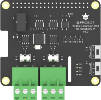
The DFRobot_RS485 Expansion HAT is a hardware add-on designed for Raspberry Pi, enabling RS485 communication. RS485 is a robust communication standard widely used in industrial environments for long-distance and noise-resistant data transmission. This HAT simplifies the integration of RS485 communication into Raspberry Pi projects, making it ideal for applications such as industrial automation, sensor networks, and building management systems.
Explore Projects Built with DFRobot_RS485 Expansion HAT for Raspberry Pi

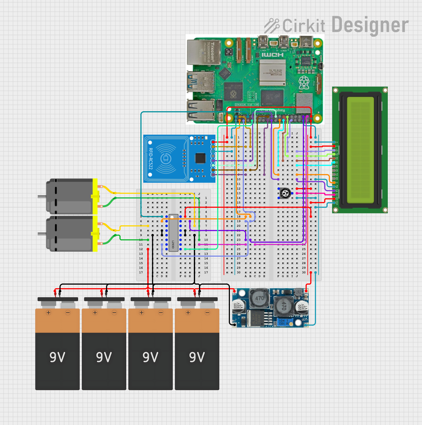
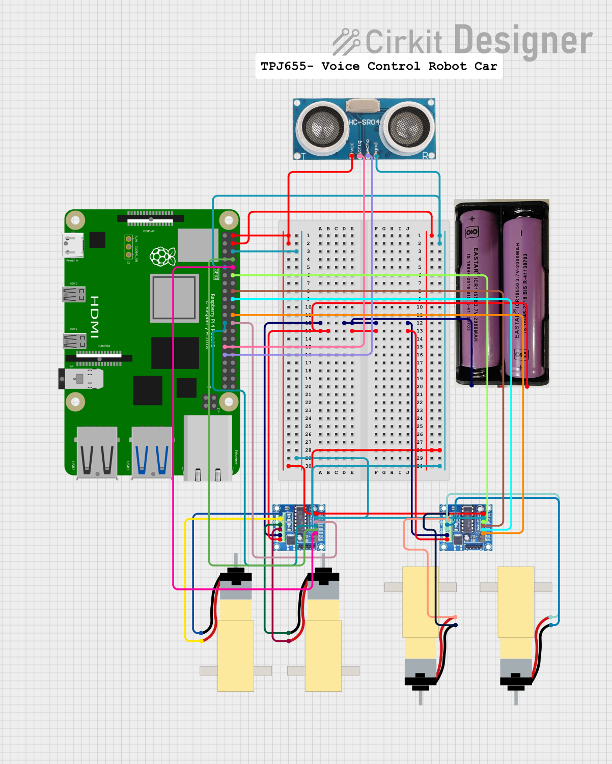

Explore Projects Built with DFRobot_RS485 Expansion HAT for Raspberry Pi
Common Applications and Use Cases
- Industrial automation and control systems
- Long-distance sensor data acquisition
- Building management systems (e.g., HVAC, lighting control)
- Communication with RS485-compatible devices like PLCs, motor controllers, and sensors
- Modbus RTU communication for industrial protocols
Technical Specifications
The DFRobot_RS485 Expansion HAT is designed to provide reliable and efficient RS485 communication. Below are its key technical details:
Key Technical Details
- Manufacturer: DFRobot
- Part ID: RS485 module
- Communication Protocol: RS485
- Input Voltage: 3.3V or 5V (via Raspberry Pi GPIO)
- Baud Rate: Up to 115200 bps
- Operating Temperature: -40°C to 85°C
- Dimensions: 65mm x 56mm
- Connector Type: Terminal block for RS485 wiring
- Compatibility: Raspberry Pi 4B/3B+/3B/2B/Zero/Zero W
Pin Configuration and Descriptions
The RS485 Expansion HAT connects to the Raspberry Pi via the GPIO header. Below is the pin configuration:
| Pin Name | Pin Number | Description |
|---|---|---|
| 5V | 2 | Power supply (5V input) |
| 3.3V | 1 | Power supply (3.3V input) |
| GND | 6 | Ground |
| TXD | 8 | UART Transmit (RS485 Data Out) |
| RXD | 10 | UART Receive (RS485 Data In) |
| DE/RE | GPIO17 (Pin 11) | RS485 Driver Enable/Receiver Enable |
Usage Instructions
The DFRobot_RS485 Expansion HAT is easy to set up and use with a Raspberry Pi. Follow the steps below to integrate it into your project:
Step 1: Hardware Setup
- Attach the HAT: Align the RS485 Expansion HAT with the Raspberry Pi GPIO header and press it down gently to ensure a secure connection.
- Connect RS485 Wires: Use the terminal block on the HAT to connect the RS485 A(+) and B(-) lines to your RS485 network.
- Power the Raspberry Pi: Ensure the Raspberry Pi is powered via its standard power supply.
Step 2: Software Configuration
- Enable UART:
- Open the Raspberry Pi configuration tool:
sudo raspi-config - Navigate to
Interfacing Options > Serial Port. - Disable the login shell over serial and enable the serial port hardware.
- Open the Raspberry Pi configuration tool:
- Install Required Libraries: Install Python libraries for serial communication:
sudo apt update
sudo apt install python3-serial
Step 3: Example Code
Below is an example Python script to send and receive data over RS485 using the HAT:
import serial
import time
Initialize serial communication
Replace '/dev/ttyS0' with the correct UART port for your Raspberry Pi
ser = serial.Serial( port='/dev/ttyS0', # UART port baudrate=9600, # Baud rate parity=serial.PARITY_NONE, stopbits=serial.STOPBITS_ONE, bytesize=serial.EIGHTBITS, timeout=1 # Timeout in seconds )
try: while True: # Send data over RS485 ser.write(b'Hello RS485!\n') # Send a message print("Message sent: Hello RS485!")
    # Wait for a response
    time.sleep(1)
    if ser.in_waiting > 0:  # Check if data is available
        response = ser.read(ser.in_waiting).decode('utf-8')
        print(f"Received: {response}")
except KeyboardInterrupt: print("Exiting program...") finally: ser.close() # Close the serial port
Important Considerations and Best Practices
- Termination Resistor: If the RS485 network is long or has multiple devices, ensure proper termination resistors are used to prevent signal reflections.
- Baud Rate Matching: Ensure all devices on the RS485 network use the same baud rate.
- Grounding: Connect the GND of the RS485 HAT to the GND of the RS485 network for proper signal reference.
- Driver Enable Pin: The DE/RE pin is controlled automatically by the HAT, but ensure GPIO17 is not used for other purposes in your project.
Troubleshooting and FAQs
Common Issues and Solutions
No Data Transmission or Reception:
- Verify the RS485 A(+) and B(-) lines are correctly connected.
- Check the UART port configuration and ensure the correct port is used in the code.
- Ensure the baud rate and other serial settings match across all devices.
Data Corruption:
- Check for proper termination resistors at both ends of the RS485 network.
- Ensure the cable length and quality are suitable for RS485 communication.
HAT Not Detected:
- Ensure the HAT is securely connected to the Raspberry Pi GPIO header.
- Verify that UART is enabled in the Raspberry Pi configuration.
FAQs
Q: Can I use this HAT with other single-board computers?
A: The HAT is designed for Raspberry Pi GPIO headers. However, it may work with other boards that have compatible UART pins, but additional wiring and configuration may be required.
Q: What is the maximum communication distance for RS485?
A: RS485 supports communication distances of up to 1200 meters, depending on the cable quality and baud rate.
Q: Can I use this HAT for Modbus RTU communication?
A: Yes, the HAT supports Modbus RTU communication. You can use Python libraries like pymodbus to implement Modbus protocols.
Q: How do I identify the UART port on my Raspberry Pi?
A: On most Raspberry Pi models, the UART port is /dev/ttyS0 or /dev/serial0. Use the command ls /dev/serial* to list available serial ports.
By following this documentation, you can effectively integrate the DFRobot_RS485 Expansion HAT into your Raspberry Pi projects for reliable RS485 communication.