
How to Use PowerBoost 500 Charger: Examples, Pinouts, and Specs
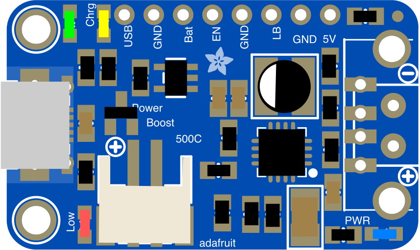
 Design with PowerBoost 500 Charger in Cirkit Designer
Introduction
The PowerBoost 500 Charger by Adafruit is a compact and efficient power management module designed to boost voltage from a lower input source to a stable 5V output. It is ideal for powering USB devices or charging lithium polymer (LiPo) or lithium-ion batteries. With its high output current capability and integrated protection features, the PowerBoost 500 Charger is a versatile solution for portable electronics, DIY projects, and battery-powered systems.
Explore Projects Built with PowerBoost 500 Charger
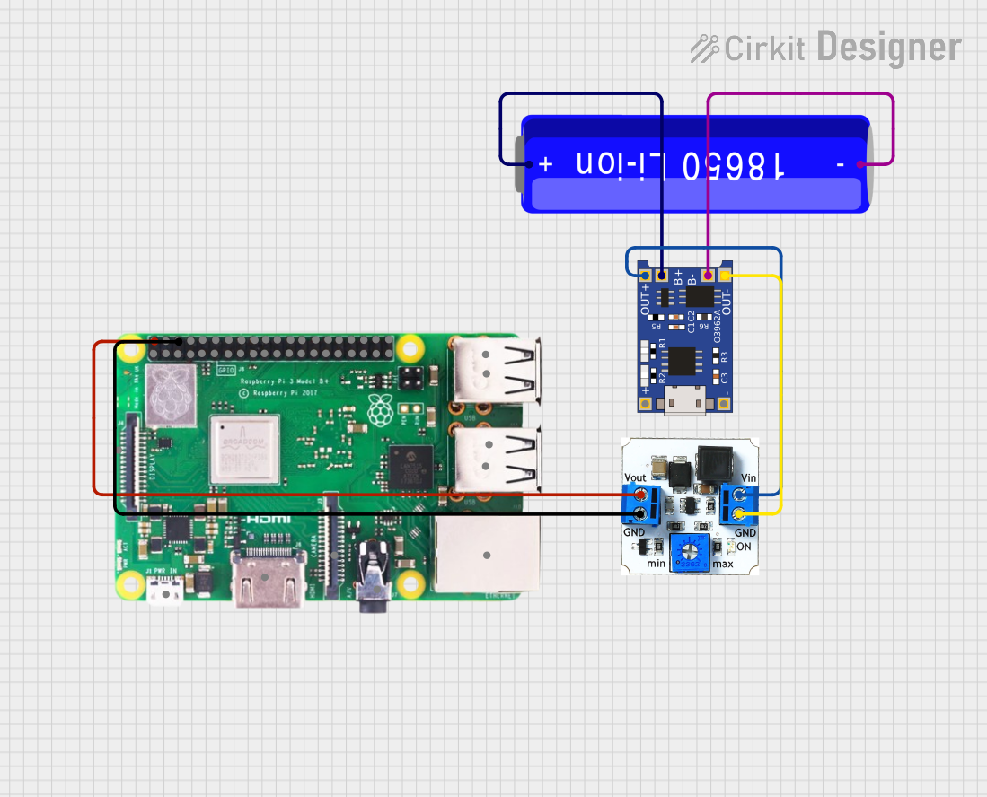 Open Project in Cirkit Designer
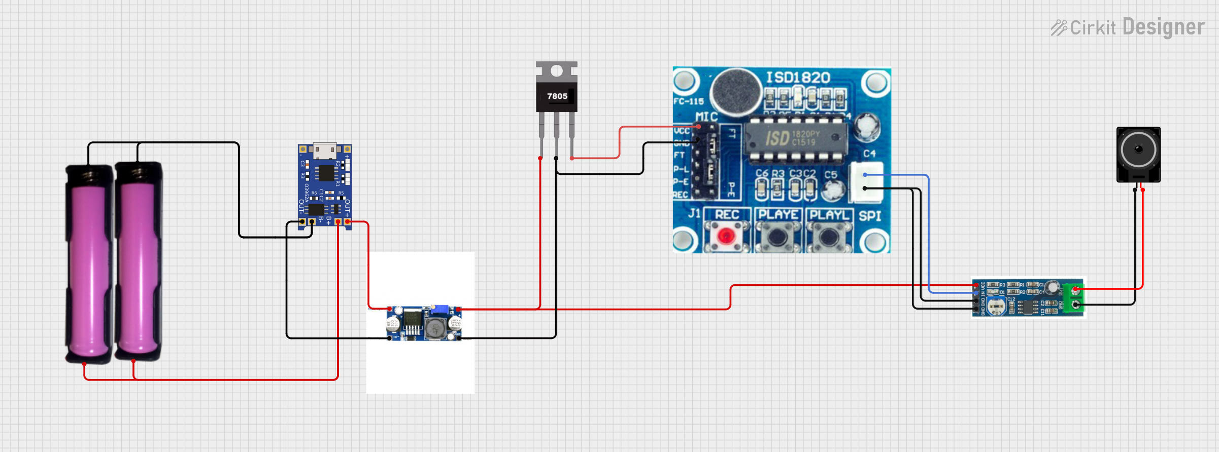 Open Project in Cirkit Designer
 Open Project in Cirkit Designer
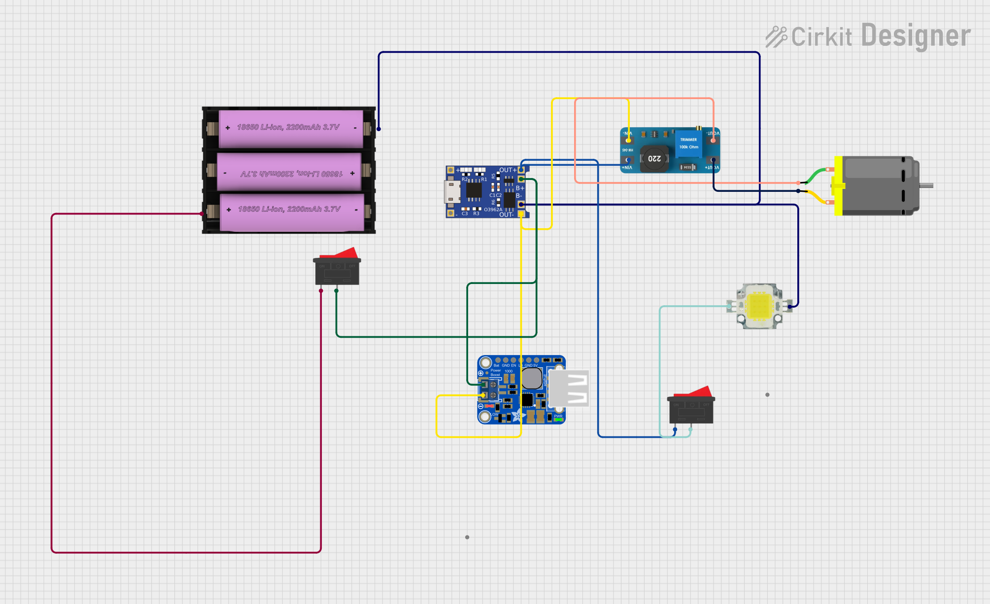 Open Project in Cirkit Designer
Explore Projects Built with PowerBoost 500 Charger
Open Project in Cirkit DesignerOpen Project in Cirkit DesignerOpen Project in Cirkit DesignerOpen Project in Cirkit DesignerCommon Applications and Use Cases
- Powering USB devices from a single-cell LiPo or lithium-ion battery
- Portable electronics and wearable devices
- DIY power banks and battery backup systems
- Robotics and embedded systems
- Arduino and Raspberry Pi projects requiring a stable 5V supply
Technical Specifications
The following table outlines the key technical details of the PowerBoost 500 Charger:
| Parameter | Value |
|---|---|
| Input Voltage Range | 1.8V to 5.5V |
| Output Voltage | 5.2V (regulated) |
| Maximum Output Current | 500mA (continuous), 1A (peak) |
| Efficiency | Up to 90% |
| Battery Charging Current | 500mA |
| Protection Features | Overcurrent, overtemperature, low-battery shutdown |
| Dimensions | 22mm x 22mm x 5mm |
Pin Configuration and Descriptions
The PowerBoost 500 Charger has the following pinout:
| Pin Name | Type | Description |
|---|---|---|
| BAT | Input | Connect to the positive terminal of a single-cell LiPo or lithium-ion battery. |
| GND | Ground | Common ground for input, output, and battery. |
| USB | Input | Micro-USB connector for charging the battery or powering the module. |
| 5V | Output | Regulated 5.2V output for powering devices. |
| EN | Input (Active Low) | Enable pin. Pull low to disable the output. Leave floating or pull high to enable. |
| LBO | Output | Low-battery output signal. Goes low when the battery voltage is critically low. |
| LBI | Input | Low-battery input threshold. Connect to a voltage divider to set the threshold. |
Usage Instructions
How to Use the PowerBoost 500 Charger in a Circuit
- Power Input: Connect a single-cell LiPo or lithium-ion battery to the
BATpin. Alternatively, you can power the module via the micro-USB connector. - Output Connection: Connect your load (e.g., Arduino, Raspberry Pi, or USB device) to the
5Voutput pin andGND. - Enable/Disable: Use the
ENpin to control the output. Pull it low to disable the output or leave it floating to enable. - Low-Battery Monitoring: Use the
LBOpin to monitor the battery status. When the battery voltage drops below the threshold, theLBOpin will go low, signaling a low-battery condition.
Important Considerations and Best Practices
- Battery Selection: Use only single-cell LiPo or lithium-ion batteries with a nominal voltage of 3.7V.
- Heat Dissipation: The module may heat up under high loads. Ensure proper ventilation or heat sinking if operating near the maximum current.
- Output Voltage: The output is regulated at 5.2V to compensate for voltage drops in USB cables. This is safe for most 5V devices.
- Charging: When connected to a USB power source, the module will charge the battery at a rate of 500mA. Ensure your battery can handle this charging current.
Example: Using with an Arduino UNO
The PowerBoost 500 Charger can be used to power an Arduino UNO. Below is an example circuit and code to monitor the low-battery signal.
Circuit Connections
- Connect the
5Voutput of the PowerBoost to the5Vpin on the Arduino UNO. - Connect
GNDof the PowerBoost to theGNDpin on the Arduino UNO. - Connect the
LBOpin of the PowerBoost to a digital input pin (e.g., pin 2) on the Arduino UNO.
Arduino Code
const int lboPin = 2; // Pin connected to the LBO pin of the PowerBoost
const int ledPin = 13; // Built-in LED to indicate low battery

void setup() {
  pinMode(lboPin, INPUT); // Set LBO pin as input
  pinMode(ledPin, OUTPUT); // Set LED pin as output
  digitalWrite(ledPin, LOW); // Turn off LED initially
  Serial.begin(9600); // Initialize serial communication
}

void loop() {
  int lboState = digitalRead(lboPin); // Read the state of the LBO pin

  if (lboState == LOW) {
    // If LBO pin is LOW, battery is critically low
    digitalWrite(ledPin, HIGH); // Turn on LED
    Serial.println("Warning: Low battery detected!");
  } else {
    // If LBO pin is HIGH, battery is okay
    digitalWrite(ledPin, LOW); // Turn off LED
    Serial.println("Battery level is sufficient.");
  }

  delay(1000); // Wait for 1 second before checking again
}
Troubleshooting and FAQs
Common Issues and Solutions
Module Overheating
- Cause: High current draw or insufficient ventilation.
- Solution: Reduce the load or improve airflow around the module.
Output Voltage Dropping Below 5V
- Cause: Battery voltage is too low or load exceeds the module's capacity.
- Solution: Recharge the battery or reduce the load.
Battery Not Charging
- Cause: Faulty battery connection or insufficient USB power supply.
- Solution: Check the battery connections and ensure the USB power source can supply at least 500mA.
LBO Pin Always Low
- Cause: Battery voltage is below the low-battery threshold.
- Solution: Recharge the battery or adjust the low-battery threshold using the
LBIpin.
FAQs
Q: Can I use the PowerBoost 500 Charger without a battery?
A: Yes, you can power the module directly via the USB input. However, the low-battery features will not function.
Q: Is the output safe for USB devices?
A: Yes, the output is regulated at 5.2V, which is within the safe range for USB devices.
Q: Can I use this module with a 2-cell LiPo battery?
A: No, the PowerBoost 500 Charger is designed for single-cell LiPo or lithium-ion batteries only.
Q: What happens if the battery voltage drops too low?
A: The module will automatically shut down to protect the battery from over-discharge.