Cirkit Designer Logo
Cirkit Designer
Your all-in-one circuit design IDE
Home / 
Component Documentation

How to Use SR602 : Examples, Pinouts, and Specs

Image of SR602
Cirkit Designer LogoDesign with SR602 in Cirkit Designer

Introduction

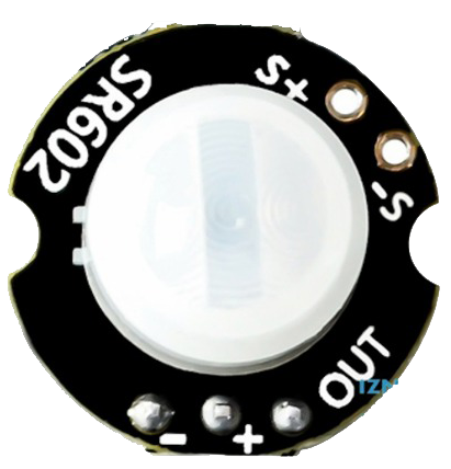
The SR602 (Manufacturer Part ID: MH-SR602) is a low-power, dual-channel infrared receiver module designed and manufactured by ABC-RC. It is optimized for remote control applications, operating at a frequency of 38 kHz. The SR602 is capable of receiving signals from infrared remote controls, making it an essential component for consumer electronics, home automation systems, and other IR-based communication projects.

Explore Projects Built with SR602

Use Cirkit Designer to design, explore, and prototype these projects online. Some projects support real-time simulation. Click "Open Project" to start designing instantly!
Battery-Powered Emergency Alert System with NUCLEO-F072RB, SIM800L, and GPS NEO 6M
Image of women safety: A project utilizing SR602  in a practical application
This circuit is an emergency alert system that uses a NUCLEO-F072RB microcontroller to send SMS alerts and make calls via a SIM800L GSM module, while obtaining location data from a GPS NEO 6M module. The system is powered by a Li-ion battery and includes a TP4056 module for battery charging and protection, with a rocker switch to control power to the microcontroller.
Cirkit Designer LogoOpen Project in Cirkit Designer
Satellite-Based Timing and Navigation System with SDR and Atomic Clock Synchronization
Image of GPS 시스템 측정 구성도_Confirm: A project utilizing SR602  in a practical application
This circuit appears to be a complex system involving power supply management, GPS and timing synchronization, and data communication. It includes a SI-TEX G1 Satellite Compass for GPS data, an XHTF1021 Atomic Rubidium Clock for precise timing, and Ettus USRP B200 units for software-defined radio communication. Power is supplied through various SMPS units and distributed via terminal blocks and DC jacks. Data communication is facilitated by Beelink MINI S12 N95 computers, RS232 splitters, and a 1000BASE-T Media Converter for network connectivity. RF Directional Couplers are used to interface antennas with the USRP units, and the entire system is likely contained within cases for protection and organization.
Cirkit Designer LogoOpen Project in Cirkit Designer
Arduino UNO-Based Force Sensing System with Bluetooth and MPU6050
Image of shoe: A project utilizing SR602  in a practical application
This circuit is designed to measure force using multiple force sensing resistors (FSRs) and transmit the data wirelessly via an HC-05 Bluetooth module. An Arduino UNO microcontroller reads the analog signals from the FSRs, processes the data, and communicates with the MPU6050 sensor for additional motion sensing capabilities.
Cirkit Designer LogoOpen Project in Cirkit Designer
ESP32-Based Remote-Controlled Servo System with GPS and IMU Integration
Image of RC Plane: A project utilizing SR602  in a practical application
This circuit integrates an ESP32 microcontroller with an AR610 receiver, an MPU-6050 accelerometer, a Neo 6M GPS module, and multiple servos. The ESP32 processes input signals from the AR610 receiver and MPU-6050, while controlling the servos and receiving GPS data for navigation or control purposes.
Cirkit Designer LogoOpen Project in Cirkit Designer

Explore Projects Built with SR602

Use Cirkit Designer to design, explore, and prototype these projects online. Some projects support real-time simulation. Click "Open Project" to start designing instantly!
Image of women safety: A project utilizing SR602  in a practical application
Battery-Powered Emergency Alert System with NUCLEO-F072RB, SIM800L, and GPS NEO 6M
This circuit is an emergency alert system that uses a NUCLEO-F072RB microcontroller to send SMS alerts and make calls via a SIM800L GSM module, while obtaining location data from a GPS NEO 6M module. The system is powered by a Li-ion battery and includes a TP4056 module for battery charging and protection, with a rocker switch to control power to the microcontroller.
Cirkit Designer LogoOpen Project in Cirkit Designer
Image of GPS 시스템 측정 구성도_Confirm: A project utilizing SR602  in a practical application
Satellite-Based Timing and Navigation System with SDR and Atomic Clock Synchronization
This circuit appears to be a complex system involving power supply management, GPS and timing synchronization, and data communication. It includes a SI-TEX G1 Satellite Compass for GPS data, an XHTF1021 Atomic Rubidium Clock for precise timing, and Ettus USRP B200 units for software-defined radio communication. Power is supplied through various SMPS units and distributed via terminal blocks and DC jacks. Data communication is facilitated by Beelink MINI S12 N95 computers, RS232 splitters, and a 1000BASE-T Media Converter for network connectivity. RF Directional Couplers are used to interface antennas with the USRP units, and the entire system is likely contained within cases for protection and organization.
Cirkit Designer LogoOpen Project in Cirkit Designer
Image of shoe: A project utilizing SR602  in a practical application
Arduino UNO-Based Force Sensing System with Bluetooth and MPU6050
This circuit is designed to measure force using multiple force sensing resistors (FSRs) and transmit the data wirelessly via an HC-05 Bluetooth module. An Arduino UNO microcontroller reads the analog signals from the FSRs, processes the data, and communicates with the MPU6050 sensor for additional motion sensing capabilities.
Cirkit Designer LogoOpen Project in Cirkit Designer
Image of RC Plane: A project utilizing SR602  in a practical application
ESP32-Based Remote-Controlled Servo System with GPS and IMU Integration
This circuit integrates an ESP32 microcontroller with an AR610 receiver, an MPU-6050 accelerometer, a Neo 6M GPS module, and multiple servos. The ESP32 processes input signals from the AR610 receiver and MPU-6050, while controlling the servos and receiving GPS data for navigation or control purposes.
Cirkit Designer LogoOpen Project in Cirkit Designer

Common Applications

  • Remote control signal reception for TVs, audio systems, and set-top boxes
  • Home automation systems for IR-based device control
  • Robotics and IoT projects requiring IR communication
  • Consumer electronics with IR-based user interfaces

Technical Specifications

The SR602 is designed to provide reliable performance in a compact form factor. Below are its key technical specifications:

Parameter Value
Operating Voltage 3.3V to 5.5V
Operating Current ≤ 1.5 mA
Carrier Frequency 38 kHz
Reception Distance Up to 18 meters (line of sight)
Reception Angle ±45°
Output Signal Digital (active low)
Operating Temperature -25°C to +85°C
Dimensions 10mm x 5mm x 3mm

Pin Configuration and Descriptions

The SR602 module has three pins, as described in the table below:

Pin Name Description
1 VCC Power supply input (3.3V to 5.5V). Connect to the positive terminal of the power source.
2 GND Ground. Connect to the negative terminal of the power source.
3 OUT Digital output pin. Outputs a low signal when an IR signal is detected.

Usage Instructions

The SR602 is straightforward to use in a circuit. Follow the steps below to integrate it into your project:

  1. Power the Module: Connect the VCC pin to a 3.3V or 5V power source and the GND pin to ground.
  2. Connect the Output: Connect the OUT pin to a microcontroller or other digital input device. The output will be active low, meaning it will go low (0V) when an IR signal is detected.
  3. Positioning: Ensure the module is positioned to face the IR transmitter directly for optimal signal reception. Avoid obstructions between the transmitter and receiver.
  4. Decoding the Signal: Use a microcontroller (e.g., Arduino UNO) to decode the received IR signal. Libraries such as the IRremote library for Arduino can simplify this process.

Example: Connecting SR602 to an Arduino UNO

Below is an example of how to connect and use the SR602 with an Arduino UNO to decode IR signals:

Circuit Diagram

  • VCC: Connect to the Arduino's 5V pin.
  • GND: Connect to the Arduino's GND pin.
  • OUT: Connect to Arduino digital pin 2.

Arduino Code

#include <IRremote.h> // Include the IRremote library

const int RECV_PIN = 2; // Define the pin connected to the SR602 OUT pin
IRrecv irrecv(RECV_PIN); // Create an IR receiver object
decode_results results;  // Variable to store decoded IR data

void setup() {
  Serial.begin(9600); // Initialize serial communication
  irrecv.enableIRIn(); // Start the IR receiver
  Serial.println("IR Receiver is ready");
}

void loop() {
  if (irrecv.decode(&results)) { // Check if an IR signal is received
    Serial.print("IR Code: ");
    Serial.println(results.value, HEX); // Print the received IR code in hexadecimal
    irrecv.resume(); // Prepare to receive the next signal
  }
}

Important Considerations

  • Power Supply: Ensure a stable power supply to avoid erratic behavior.
  • Interference: Avoid placing the module near sources of IR interference, such as sunlight or fluorescent lights.
  • Signal Decoding: Use appropriate libraries or algorithms to decode the received IR signals accurately.

Troubleshooting and FAQs

Common Issues and Solutions

  1. No Signal Detected:

    • Ensure the IR transmitter is functioning and pointed directly at the SR602.
    • Check the wiring connections, especially the VCC and GND pins.
    • Verify that the power supply voltage is within the specified range (3.3V to 5.5V).
  2. Erratic or Unreliable Output:

    • Minimize interference from ambient light sources.
    • Ensure the module is not placed too far from the IR transmitter (maximum range is 18 meters).
  3. Output Always Low:

    • Check if the IR transmitter is continuously sending signals.
    • Verify that the OUT pin is correctly connected to the microcontroller.
  4. Output Always High:

    • Ensure the IR transmitter is active and sending signals.
    • Confirm that the SR602 is receiving sufficient power.

FAQs

Q1: Can the SR602 work with 3.3V microcontrollers like ESP32?
A1: Yes, the SR602 operates within a voltage range of 3.3V to 5.5V, making it compatible with 3.3V microcontrollers.

Q2: What is the maximum distance for reliable signal reception?
A2: The SR602 can reliably receive signals up to 18 meters in a direct line of sight.

Q3: Can the SR602 detect signals from any IR remote?
A3: The SR602 is designed to detect signals modulated at 38 kHz, which is the standard for most IR remote controls.

Q4: How do I decode complex IR protocols?
A4: Use libraries like IRremote for Arduino or similar tools for other platforms to decode complex IR protocols easily.

By following this documentation, you can effectively integrate the SR602 into your projects and troubleshoot any issues that arise.