How to Use CANISO: Examples, Pinouts, and Specs
Introduction
The CANISO is a communication interface that integrates Controller Area Network (CAN) functionality with ISO standards for enhanced reliability and safety. It is designed to facilitate robust and efficient data exchange in demanding environments such as automotive, industrial automation, and medical systems. By combining the high-speed communication capabilities of CAN with the isolation and safety features of ISO standards, the CANISO ensures data integrity and protection against electrical noise and surges.
Explore Projects Built with CANISO
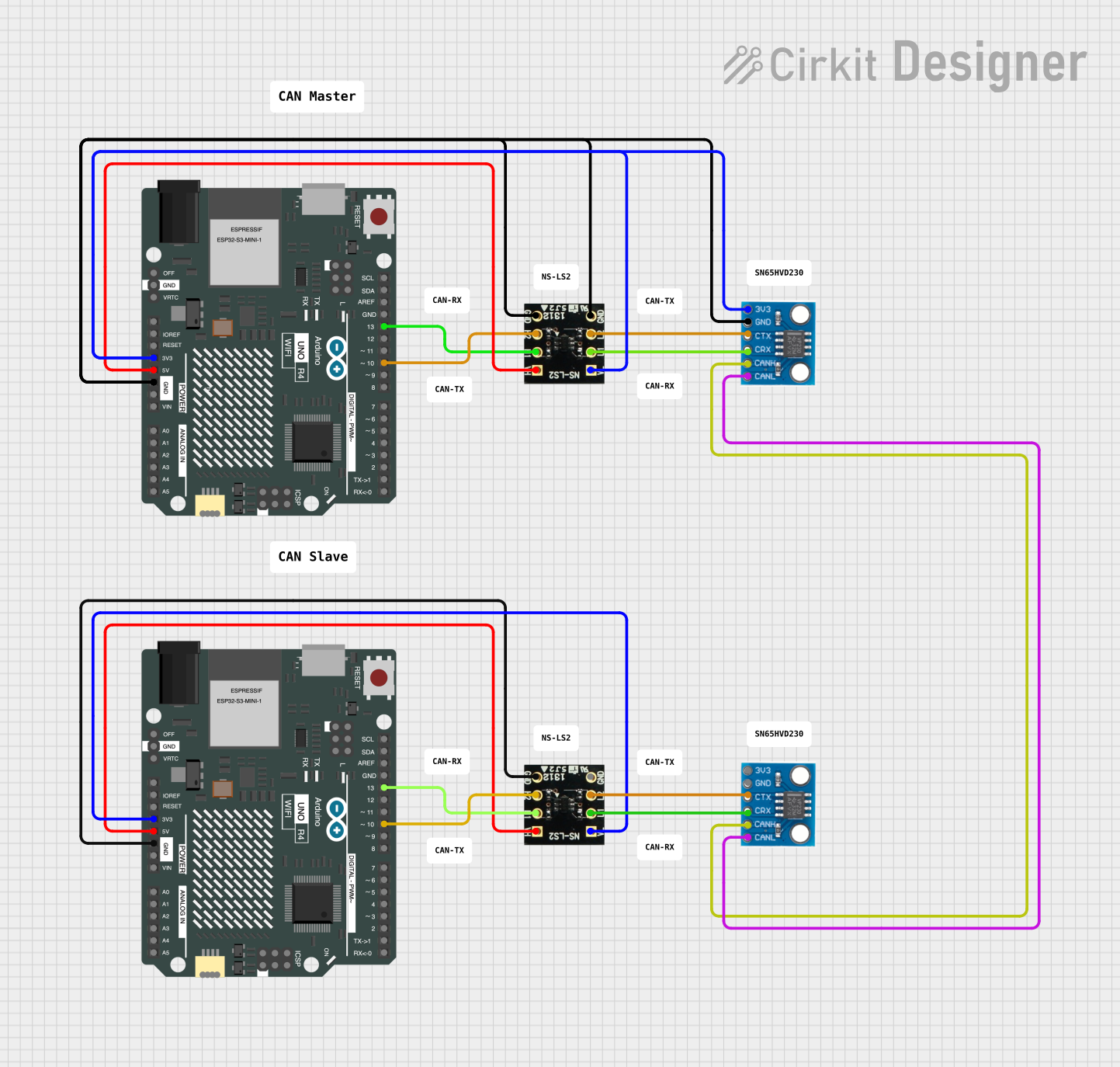
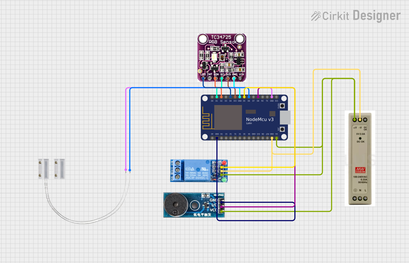
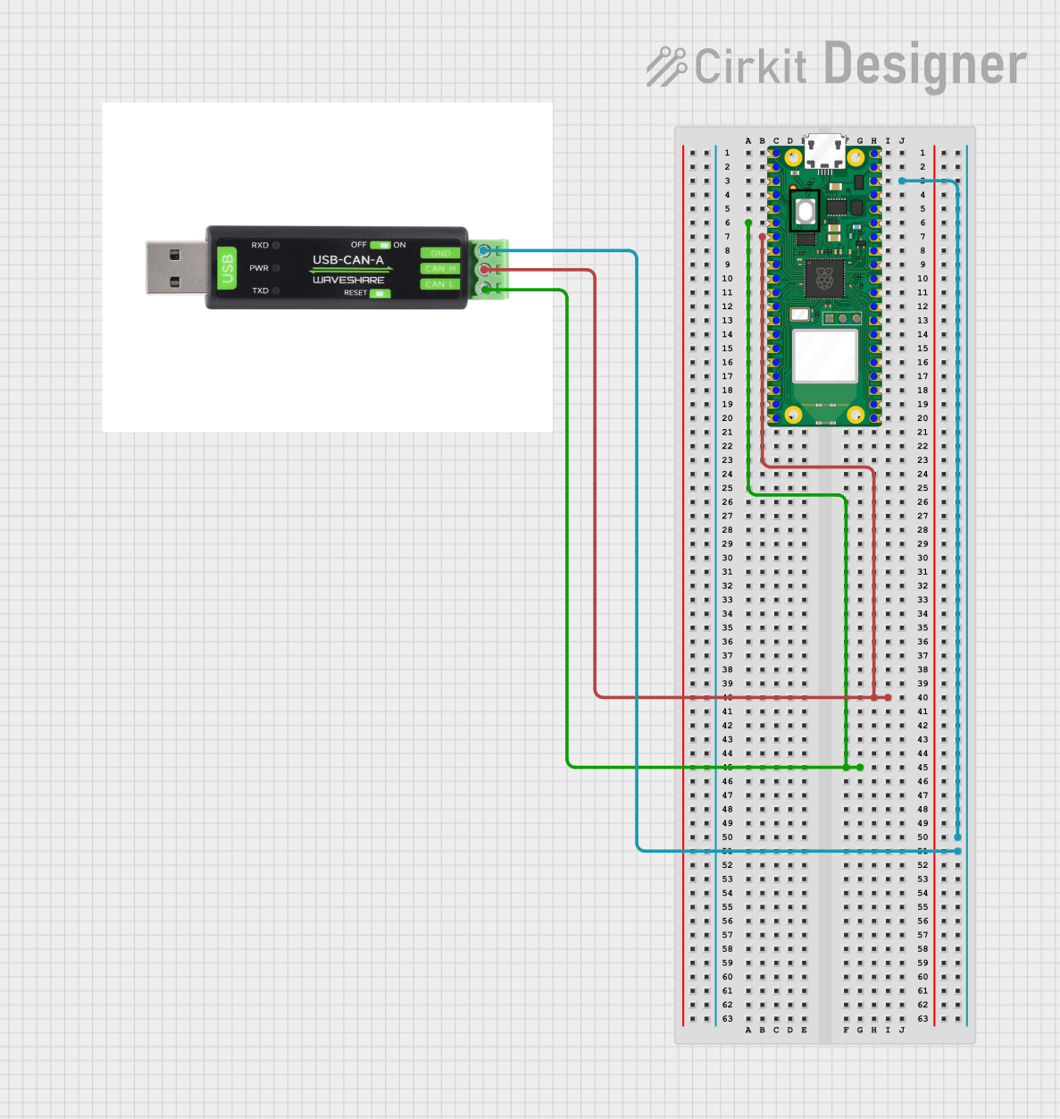
Explore Projects Built with CANISO
Common Applications
- Automotive systems (e.g., engine control units, infotainment systems)
- Industrial automation (e.g., PLCs, motor controllers)
- Medical devices requiring isolated communication
- Renewable energy systems (e.g., solar inverters, battery management systems)
Technical Specifications
Key Technical Details
| Parameter | Value |
|---|---|
| Supply Voltage (Vcc) | 3.3V or 5V |
| Data Rate | Up to 1 Mbps (Classical CAN) |
| Isolation Voltage | 2500 VRMS |
| Operating Temperature | -40°C to +125°C |
| Bus Interface | CAN (ISO 11898-2 compliant) |
| Power Consumption | < 50 mW |
| Package Type | SOIC-8, SOIC-16, or DIP-8 |
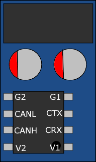
Pin Configuration and Descriptions
Example: 8-Pin SOIC Package
| Pin Number | Pin Name | Description |
|---|---|---|
| 1 | Vcc | Power supply input (3.3V or 5V) |
| 2 | GND | Ground connection |
| 3 | TXD | Transmit data input from the microcontroller |
| 4 | RXD | Receive data output to the microcontroller |
| 5 | CANH | High-level CAN bus line |
| 6 | CANL | Low-level CAN bus line |
| 7 | ISO_GND | Isolated ground for CAN bus side |
| 8 | ISO_Vcc | Isolated power supply for CAN bus side |
Usage Instructions
How to Use the CANISO in a Circuit
- Power Supply: Connect the Vcc pin to a 3.3V or 5V regulated power supply, and connect the GND pin to the system ground.
- Microcontroller Interface: Connect the TXD and RXD pins to the corresponding CAN transceiver pins on the microcontroller.
- CAN Bus Connection: Connect the CANH and CANL pins to the CAN bus lines. Ensure proper termination resistors (typically 120Ω) are placed at both ends of the CAN bus.
- Isolation: Use ISO_Vcc and ISO_GND to power the isolated side of the CANISO. This ensures electrical isolation between the microcontroller and the CAN bus.
Important Considerations
- Termination Resistors: Always include 120Ω termination resistors at both ends of the CAN bus to prevent signal reflections.
- Isolation Voltage: Ensure the isolation voltage rating of 2500 VRMS is not exceeded to maintain safety and reliability.
- Data Rate: Verify that the data rate does not exceed 1 Mbps for Classical CAN to ensure proper operation.
- PCB Layout: Maintain proper spacing between isolated and non-isolated sections on the PCB to avoid electrical interference.
Example Code for Arduino UNO
Below is an example of how to use the CANISO with an Arduino UNO and an MCP2515 CAN controller module:
#include <SPI.h>
#include <mcp_can.h>

// Define the SPI CS pin for the MCP2515 module
#define CAN_CS_PIN 10

// Initialize the MCP_CAN object
MCP_CAN CAN(CAN_CS_PIN);

void setup() {
  Serial.begin(9600);

  // Initialize the CAN bus at 500 kbps
  if (CAN.begin(MCP_ANY, CAN_500KBPS, MCP_8MHZ) == CAN_OK) {
    Serial.println("CAN bus initialized successfully!");
  } else {
    Serial.println("CAN bus initialization failed!");
    while (1); // Halt execution if initialization fails
  }

  // Set the CAN bus to normal mode
  CAN.setMode(MCP_NORMAL);
  Serial.println("CAN bus set to normal mode.");
}

void loop() {
  // Example: Send a CAN message
  byte data[8] = {0x01, 0x02, 0x03, 0x04, 0x05, 0x06, 0x07, 0x08};

  if (CAN.sendMsgBuf(0x100, 0, 8, data) == CAN_OK) {
    Serial.println("Message sent successfully!");
  } else {
    Serial.println("Error sending message.");
  }

  delay(1000); // Wait 1 second before sending the next message
}
Notes:
- Ensure the MCP2515 module is properly connected to the Arduino UNO.
- The CANISO should be connected between the MCP2515 module and the CAN bus.
Troubleshooting and FAQs
Common Issues
No Communication on the CAN Bus
- Cause: Missing or incorrect termination resistors.
- Solution: Verify that 120Ω resistors are present at both ends of the CAN bus.
Data Corruption
- Cause: Electrical noise or improper grounding.
- Solution: Ensure proper grounding and use shielded cables for the CAN bus.
Overheating
- Cause: Exceeding the power or isolation voltage ratings.
- Solution: Verify that the supply voltage and isolation voltage are within specified limits.
Initialization Failure
- Cause: Incorrect SPI connections or configuration.
- Solution: Double-check the SPI wiring and ensure the MCP2515 library is correctly installed.
FAQs
Q: Can the CANISO be used with higher data rates (e.g., CAN FD)?
- A: No, the CANISO is designed for Classical CAN with data rates up to 1 Mbps. For higher data rates, consider a CAN FD-compatible transceiver.
Q: What is the purpose of the isolated power supply?
- A: The isolated power supply (ISO_Vcc and ISO_GND) ensures electrical isolation between the microcontroller and the CAN bus, protecting against voltage spikes and ground loops.
Q: Can I use the CANISO in a 12V automotive system?
- A: Yes, but ensure that the CANISO is connected to a regulated 3.3V or 5V power supply derived from the 12V system.
By following this documentation, users can effectively integrate the CANISO into their projects for reliable and isolated CAN communication.