How to Use Linear actuator: Examples, Pinouts, and Specs
Introduction
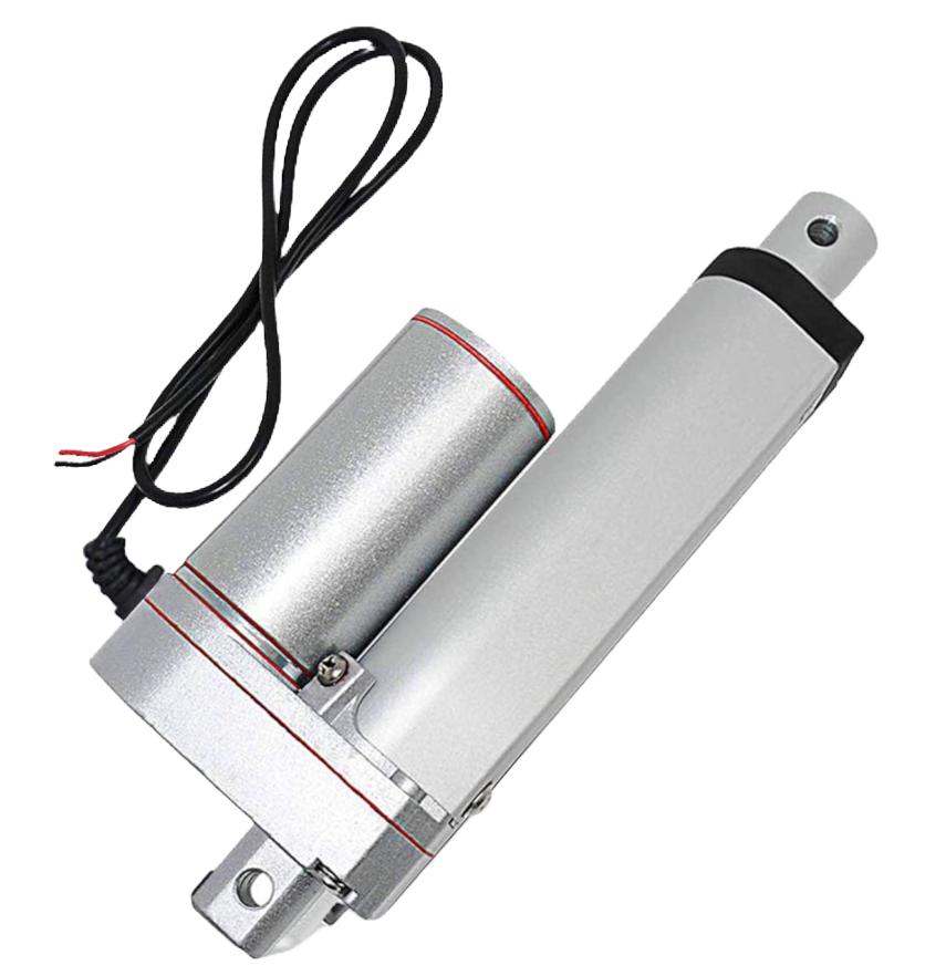
The RS Pro Linear Actuator is a robust and reliable device designed to convert rotational motion into precise linear displacement. This actuator is ideal for a wide range of applications, including robotics, automation systems, and industrial machinery where controlled linear movement is essential.
Explore Projects Built with Linear actuator
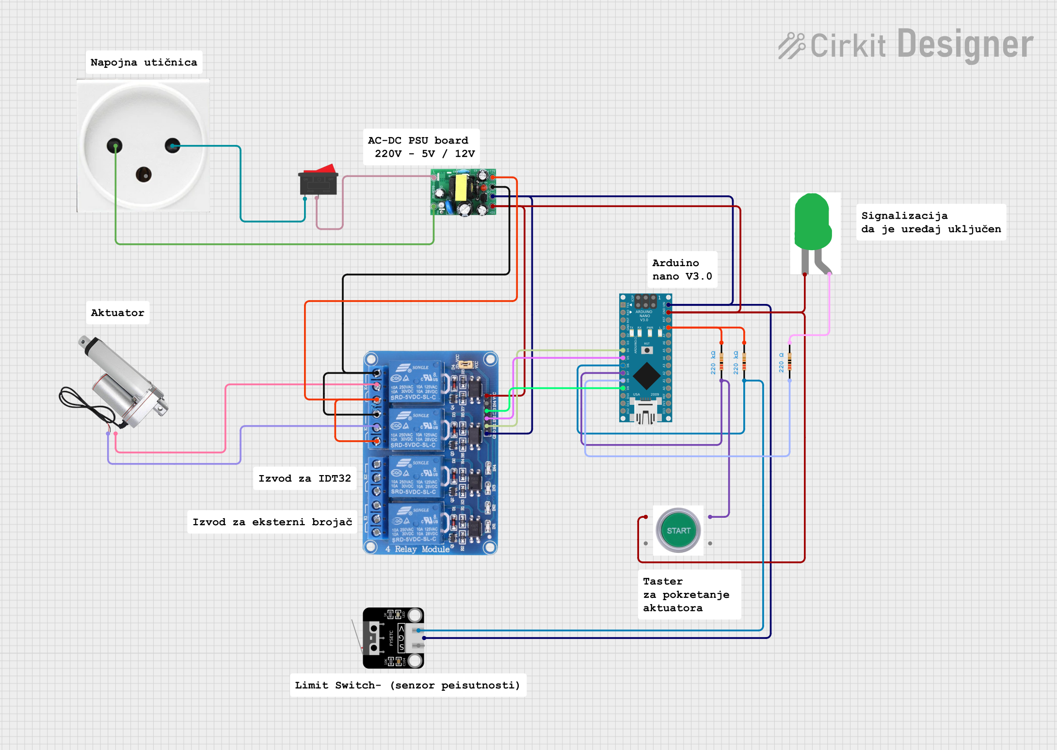
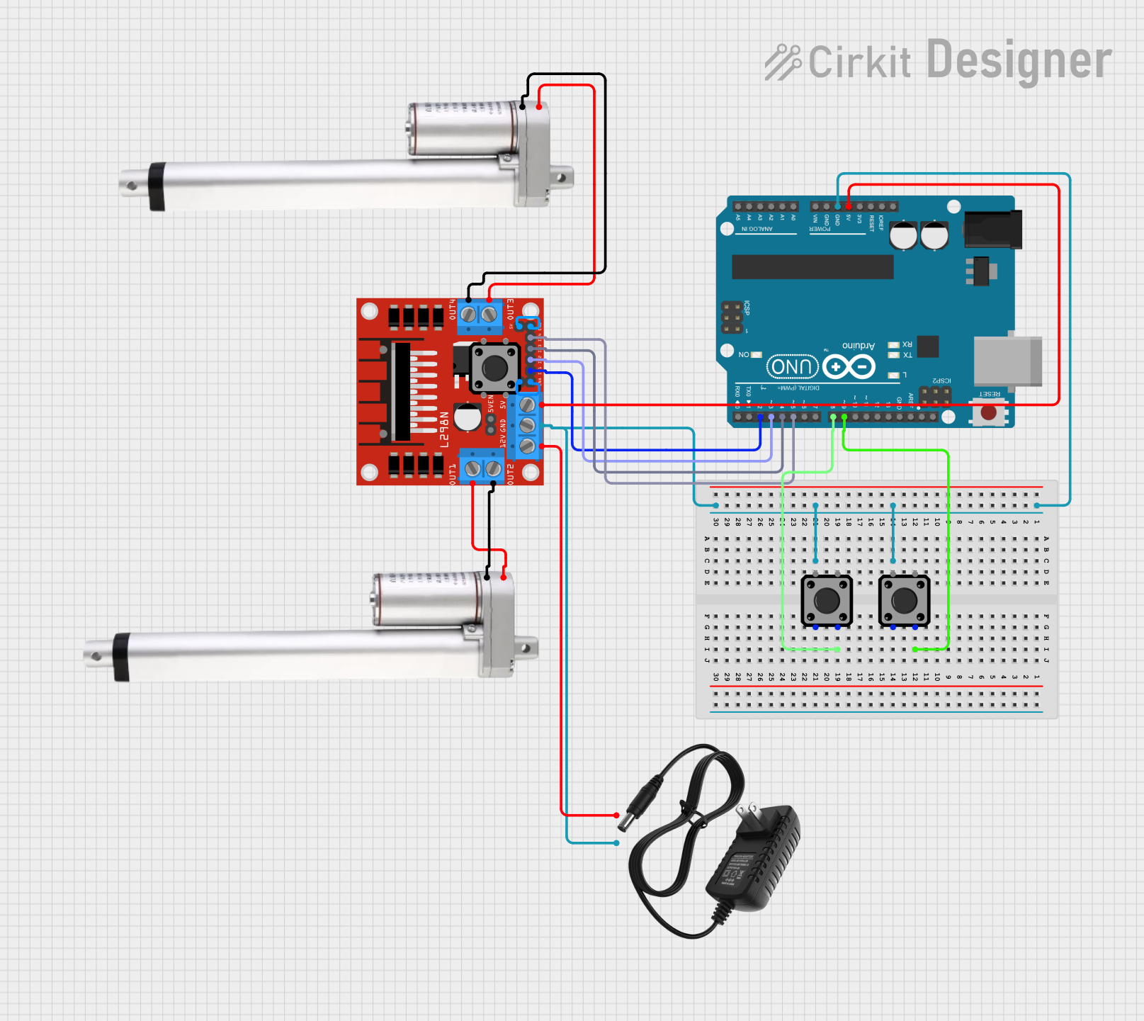
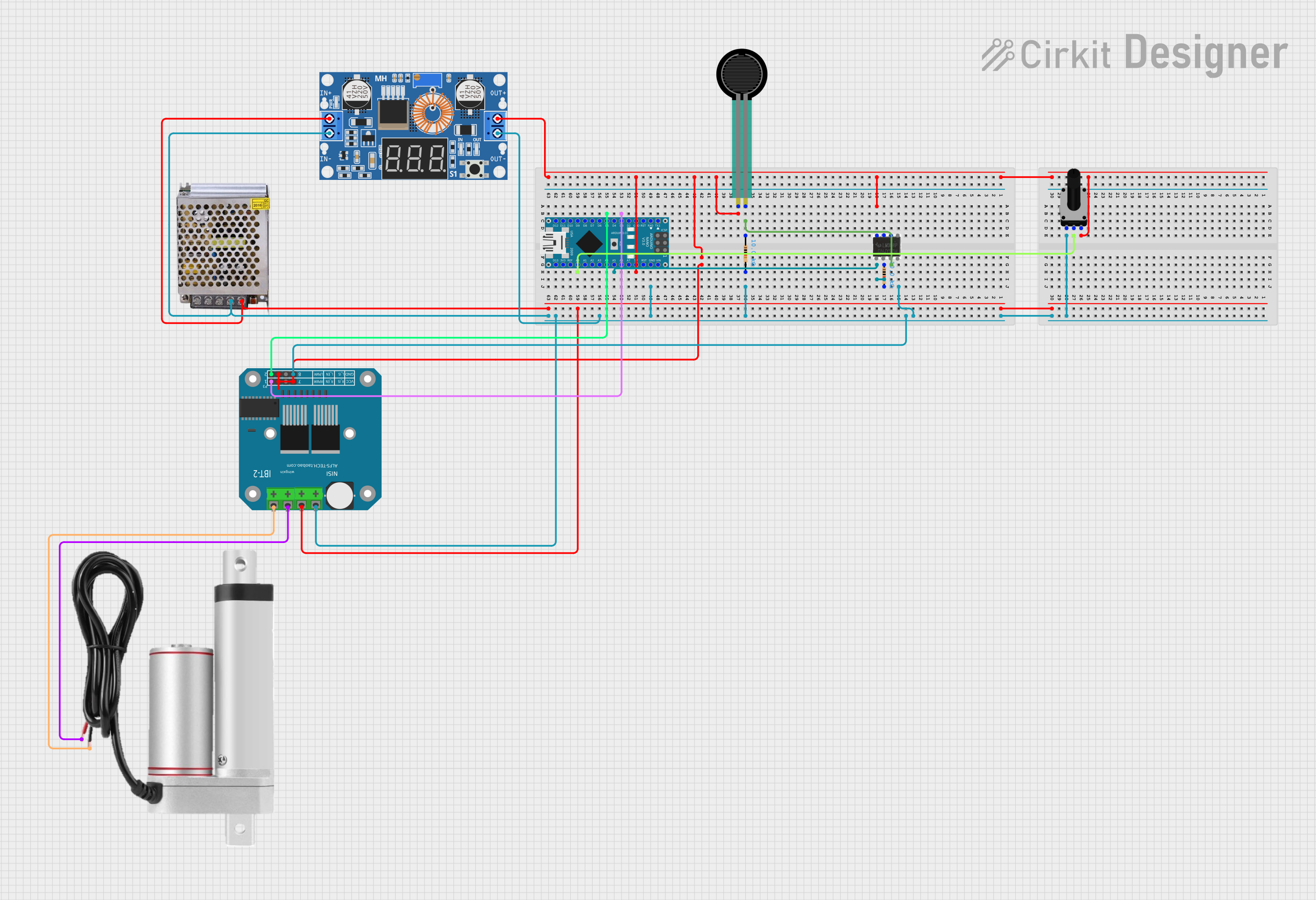
Explore Projects Built with Linear actuator
Common Applications and Use Cases
- Adjusting the height or position of a component in industrial automation
- Opening and closing valves or vents in HVAC systems
- Actuating control surfaces in aerospace applications
- Providing linear motion for 3D printers and CNC machines
- Automating sliding doors and windows
Technical Specifications
Key Technical Details
| Specification | Value | Description |
|---|---|---|
| Operating Voltage | 12V DC | Voltage required for operation |
| Static Load Capacity | Up to 1000N | Maximum load without motion |
| Dynamic Load Capacity | Up to 750N | Maximum load during motion |
| Stroke Length | 100mm to 1000mm | Range of linear movement |
| Speed | 5mm/s to 40mm/s | Speed of linear movement |
| Duty Cycle | 25% | Maximum operation time in a cycle |
| IP Rating | IP65 | Protection against dust and low-pressure jets |
Pin Configuration and Descriptions
| Pin Number | Description |
|---|---|
| 1 | Power (+12V DC) |
| 2 | Ground (0V) |
| 3 | Control Signal Input |
Usage Instructions
How to Use the Component in a Circuit
- Power Supply: Connect the power supply to the actuator, ensuring that the voltage matches the operating voltage of 12V DC.
- Control Signal: Apply a control signal to Pin 3 to initiate the actuator's movement. The nature of the control signal will depend on the actuator's control interface (e.g., PWM, analog voltage).
- Mounting: Secure the actuator to the application, ensuring that the mounting points are stable and aligned with the desired direction of motion.
Important Considerations and Best Practices
- Power Rating: Do not exceed the recommended voltage as it may damage the actuator.
- Load Capacity: Ensure that the load does not exceed the specified dynamic or static load capacity.
- Duty Cycle: Allow the actuator to rest according to its duty cycle to prevent overheating.
- Environmental Conditions: Consider the IP rating when using the actuator in environments exposed to dust or water.
- End Limits: Use end limit switches or sensors to prevent overextension or overcompression of the actuator.
Troubleshooting and FAQs
Common Issues Users Might Face
- Actuator Not Moving: Check the power supply and control signal. Ensure that the load is within the specified capacity.
- Overheating: Ensure the actuator is not operated beyond its duty cycle. Check for mechanical binding.
- Noise or Irregular Movement: This could indicate mechanical wear or an obstruction. Inspect the actuator for debris or damage.
Solutions and Tips for Troubleshooting
- Power Supply Issues: Verify the voltage and connections. Use a multimeter to check for continuity.
- Control Signal Problems: Check the signal with an oscilloscope or logic analyzer. Ensure the signal is within the specified range.
- Load Issues: Reduce the load or use a higher capacity actuator if necessary.
FAQs
Q: Can the actuator be used outdoors? A: Yes, the IP65 rating indicates that the actuator is protected against dust and low-pressure water jets, making it suitable for outdoor use.
Q: What is the lifespan of the actuator? A: The lifespan depends on the operating conditions and adherence to the duty cycle. Contact RS Pro for specific endurance ratings.
Q: How can I control the speed of the actuator? A: The speed can be controlled by varying the control signal. Refer to the manufacturer's datasheet for detailed instructions.
Q: Is it possible to synchronize multiple actuators? A: Yes, but it requires a control system capable of managing multiple actuators simultaneously. Precision synchronization may require additional feedback mechanisms.
Q: What should I do if the actuator is not extending or retracting fully? A: Check for any obstructions or misalignments. Also, verify that the end limit switches or sensors are correctly configured and functioning.
Note: This documentation is for informational purposes only. Always consult the manufacturer's datasheet and installation guide before using the actuator.