Cirkit Designer Logo
Cirkit Designer
Your all-in-one circuit design IDE
Home / 
Component Documentation

How to Use RCCB type B: Examples, Pinouts, and Specs

Image of RCCB type B
Cirkit Designer LogoDesign with RCCB type B in Cirkit Designer

Introduction

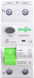
A Residual Current Circuit Breaker (RCCB) Type B is an advanced safety device designed to detect and disconnect electrical circuits in the presence of residual currents, including those with direct current (DC) components. Unlike standard RCCBs, Type B devices are capable of detecting AC, pulsating DC, and smooth DC residual currents, making them suitable for modern electrical systems with complex loads.

Explore Projects Built with RCCB type B

Use Cirkit Designer to design, explore, and prototype these projects online. Some projects support real-time simulation. Click "Open Project" to start designing instantly!
Battery-Powered Adjustable Voltage Regulator with Li-ion 18650 Batteries and BMS
Image of mini ups: A project utilizing RCCB type B in a practical application
This circuit is a power management system that uses four Li-ion 18650 batteries connected to a 2S 30A BMS for battery management and protection. The system includes step-up and step-down voltage regulators to provide adjustable output voltages, controlled by a rocker switch, and multiple DC jacks for power input and output.
Cirkit Designer LogoOpen Project in Cirkit Designer
Battery-Powered UPS with Step-Down Buck Converter and BMS
Image of Mini ups: A project utilizing RCCB type B in a practical application
This circuit is a power management system that steps down a 240V AC input to a lower DC voltage using a buck converter, which then powers a 40W UPS. The UPS is controlled by a rocker switch and is backed up by a battery management system (BMS) connected to three 3.7V batteries in series, ensuring continuous power supply.
Cirkit Designer LogoOpen Project in Cirkit Designer
NPN Transistor-Based Signal Interface with Relimate Connectors
Image of Mini cross: A project utilizing RCCB type B in a practical application
This circuit appears to be a simple transistor-based switching circuit with multiple NPN transistors and resistors, interfaced through relimate connectors. The transistors are likely used to control the flow of current through various parts of the circuit, possibly for switching or amplification purposes, with the relimate connectors providing external connections for power and signal lines.
Cirkit Designer LogoOpen Project in Cirkit Designer
18650 Li-ion Battery Pack with BMS for 5V Power Supply
Image of battary: A project utilizing RCCB type B in a practical application
This circuit consists of a battery management system (BMS) connected to a series of 18650 Li-ion batteries arranged in a 4S configuration to provide a regulated output voltage. The BMS ensures safe charging and discharging of the batteries, while a connector provides a 5V output for external devices.
Cirkit Designer LogoOpen Project in Cirkit Designer

Explore Projects Built with RCCB type B

Use Cirkit Designer to design, explore, and prototype these projects online. Some projects support real-time simulation. Click "Open Project" to start designing instantly!
Image of mini ups: A project utilizing RCCB type B in a practical application
Battery-Powered Adjustable Voltage Regulator with Li-ion 18650 Batteries and BMS
This circuit is a power management system that uses four Li-ion 18650 batteries connected to a 2S 30A BMS for battery management and protection. The system includes step-up and step-down voltage regulators to provide adjustable output voltages, controlled by a rocker switch, and multiple DC jacks for power input and output.
Cirkit Designer LogoOpen Project in Cirkit Designer
Image of Mini ups: A project utilizing RCCB type B in a practical application
Battery-Powered UPS with Step-Down Buck Converter and BMS
This circuit is a power management system that steps down a 240V AC input to a lower DC voltage using a buck converter, which then powers a 40W UPS. The UPS is controlled by a rocker switch and is backed up by a battery management system (BMS) connected to three 3.7V batteries in series, ensuring continuous power supply.
Cirkit Designer LogoOpen Project in Cirkit Designer
Image of Mini cross: A project utilizing RCCB type B in a practical application
NPN Transistor-Based Signal Interface with Relimate Connectors
This circuit appears to be a simple transistor-based switching circuit with multiple NPN transistors and resistors, interfaced through relimate connectors. The transistors are likely used to control the flow of current through various parts of the circuit, possibly for switching or amplification purposes, with the relimate connectors providing external connections for power and signal lines.
Cirkit Designer LogoOpen Project in Cirkit Designer
Image of battary: A project utilizing RCCB type B in a practical application
18650 Li-ion Battery Pack with BMS for 5V Power Supply
This circuit consists of a battery management system (BMS) connected to a series of 18650 Li-ion batteries arranged in a 4S configuration to provide a regulated output voltage. The BMS ensures safe charging and discharging of the batteries, while a connector provides a 5V output for external devices.
Cirkit Designer LogoOpen Project in Cirkit Designer

Common Applications and Use Cases

  • Electric vehicle (EV) charging stations
  • Photovoltaic (solar panel) systems
  • Industrial machinery with variable frequency drives (VFDs)
  • Medical equipment and laboratories
  • Data centers and IT infrastructure
  • Protection against electric shock and fire hazards in residential, commercial, and industrial installations

Technical Specifications

Key Technical Details

Parameter Value/Range
Rated Voltage (Un) 230V AC / 400V AC
Rated Current (In) 16A, 25A, 40A, 63A, 80A, 100A
Rated Residual Current (IΔn) 10mA, 30mA, 100mA, 300mA, 500mA
Frequency 50/60 Hz
Sensitivity AC, pulsating DC, and smooth DC
Breaking Capacity 6kA to 10kA (depending on model)
Operating Temperature -25°C to +40°C
Mounting DIN rail (35mm)
Standards Compliance IEC 61008-1, IEC 62423

Pin Configuration and Descriptions

Pin/Terminal Description
L (Line) Connects to the live wire of the input circuit
N (Neutral) Connects to the neutral wire of the input circuit
Load L Connects to the live wire of the output circuit
Load N Connects to the neutral wire of the output circuit

Usage Instructions

How to Use the RCCB Type B in a Circuit

  1. Wiring the RCCB:

    • Connect the input live wire to the L terminal and the input neutral wire to the N terminal.
    • Connect the output live wire to the Load L terminal and the output neutral wire to the Load N terminal.
    • Ensure all connections are secure and properly insulated.
  2. Testing the RCCB:

    • Use the built-in test button to verify the functionality of the RCCB. Pressing the test button should trip the breaker, disconnecting the circuit. Reset the RCCB after testing.
  3. Installation Guidelines:

    • Install the RCCB on a DIN rail in a distribution board.
    • Ensure the rated current and residual current sensitivity match the requirements of the circuit.
    • Avoid installing the RCCB in environments with excessive moisture, dust, or extreme temperatures.
  4. Connecting to an EV Charger or Solar Inverter:

    • For EV chargers, ensure the RCCB Type B is installed upstream of the charger to detect DC leakage currents.
    • For solar inverters, connect the RCCB between the inverter and the load to provide comprehensive protection.

Important Considerations and Best Practices

  • Always turn off the main power supply before installing or servicing the RCCB.
  • Use an RCCB Type B specifically for circuits with DC components, as standard RCCBs may not detect DC residual currents.
  • Periodically test the RCCB using the test button to ensure proper operation.
  • Consult a licensed electrician for installation in complex systems or high-current applications.

Troubleshooting and FAQs

Common Issues and Solutions

Issue Possible Cause Solution
RCCB does not trip during testing Faulty test button or internal mechanism Replace the RCCB
Frequent tripping of the RCCB Overload or actual residual current Check the circuit for faults or overload
RCCB does not reset after tripping Persistent fault in the circuit Inspect and repair the circuit
RCCB trips randomly Electrical noise or transient currents Use surge protection devices

FAQs

  1. Can I use an RCCB Type B for standard AC circuits?

    • Yes, but it is specifically designed for circuits with DC components. For standard AC circuits, a Type AC or Type A RCCB may be more cost-effective.
  2. How often should I test the RCCB?

    • It is recommended to test the RCCB using the test button at least once a month.
  3. What happens if I install a standard RCCB instead of Type B in a DC circuit?

    • A standard RCCB may fail to detect DC residual currents, leaving the circuit unprotected against certain faults.
  4. Can I install the RCCB Type B outdoors?

    • Only if it is housed in a weatherproof enclosure with appropriate IP ratings.

By following this documentation, users can safely and effectively utilize the RCCB Type B for enhanced electrical protection in modern systems.