How to Use 74C922: Examples, Pinouts, and Specs
Introduction
The 74C922, manufactured by Fairchild, is a dual BCD (Binary-Coded Decimal) counter designed to count from 0 to 9 in binary form. It is a versatile component that features a reset function, making it suitable for a wide range of digital counting applications. The 74C922 is commonly used in digital systems for tasks such as event counting, frequency division, and time measurement.
Explore Projects Built with 74C922

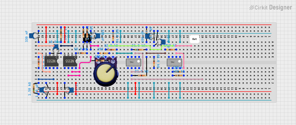

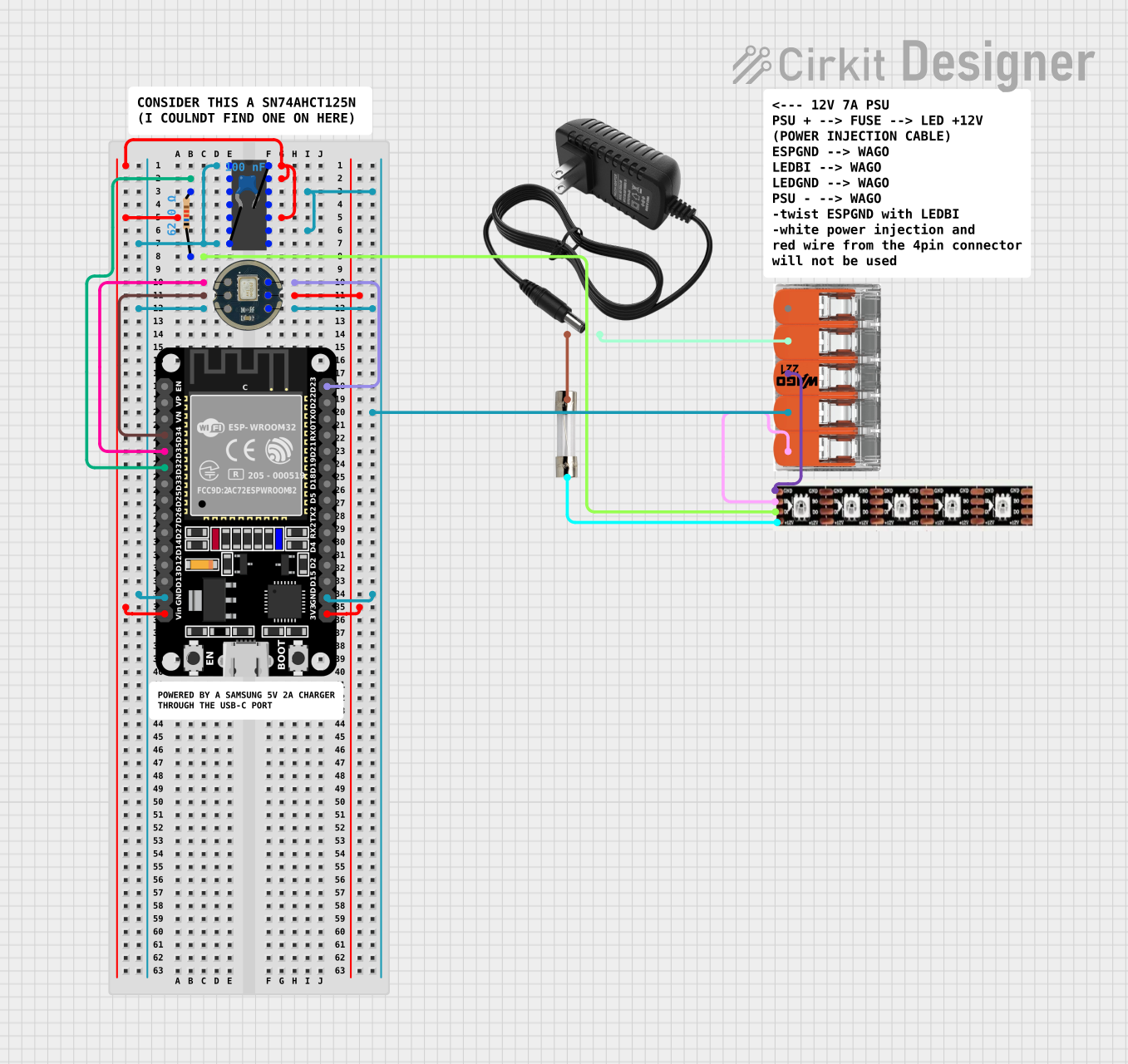
Explore Projects Built with 74C922
Common Applications
- Digital clocks and timers
- Frequency counters
- Event counters in industrial systems
- Digital display drivers
- Arithmetic and logic operations in digital circuits
Technical Specifications
Key Technical Details
- Manufacturer Part ID: 74C922
- Supply Voltage (Vcc): 3V to 15V
- Input Voltage Range: 0V to Vcc
- Maximum Clock Frequency: 5 MHz (typical at 10V supply)
- Operating Temperature Range: -40°C to +85°C
- Power Consumption: Low power CMOS technology
- Reset Function: Active-low reset pin to clear the counter
- Output Type: Binary-coded decimal (4-bit output per counter)
Pin Configuration and Descriptions
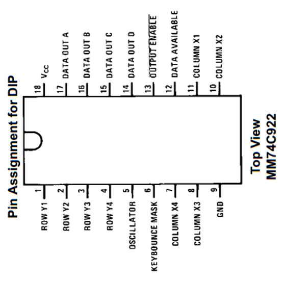
The 74C922 is a 16-pin IC. Below is the pinout and description:
| Pin Number | Pin Name | Description |
|---|---|---|
| 1 | Q1A | Output bit 1 of Counter A |
| 2 | Q2A | Output bit 2 of Counter A |
| 3 | Q3A | Output bit 3 of Counter A |
| 4 | Q4A | Output bit 4 of Counter A |
| 5 | GND | Ground |
| 6 | CLK A | Clock input for Counter A |
| 7 | RESET A | Active-low reset for Counter A |
| 8 | Vcc | Positive power supply |
| 9 | RESET B | Active-low reset for Counter B |
| 10 | CLK B | Clock input for Counter B |
| 11 | Q4B | Output bit 4 of Counter B |
| 12 | Q3B | Output bit 3 of Counter B |
| 13 | Q2B | Output bit 2 of Counter B |
| 14 | Q1B | Output bit 1 of Counter B |
| 15 | NC | No connection |
| 16 | NC | No connection |
Usage Instructions
How to Use the 74C922 in a Circuit
- Power Supply: Connect the Vcc pin (Pin 8) to a stable DC voltage source (3V to 15V) and the GND pin (Pin 5) to ground.
- Clock Input: Provide a clock signal to the CLK A (Pin 6) and/or CLK B (Pin 10) pins. The counters increment their values on the rising edge of the clock signal.
- Reset Function: To reset the counters, pull the RESET A (Pin 7) and/or RESET B (Pin 9) pins low momentarily. This clears the counter outputs to 0.
- Output Monitoring: Connect the output pins (Q1A–Q4A and Q1B–Q4B) to your desired circuit or display to monitor the binary-coded decimal count.
Important Considerations
- Ensure the clock signal does not exceed the maximum frequency of 5 MHz.
- Use pull-up or pull-down resistors on the RESET pins if they are not actively controlled.
- Decouple the power supply with a 0.1 µF capacitor near the Vcc pin to reduce noise.
- Avoid floating inputs; connect unused inputs to Vcc or GND.
Example: Connecting the 74C922 to an Arduino UNO
The 74C922 can be interfaced with an Arduino UNO to count pulses and display the count on the serial monitor. Below is an example code:
// Example: Interfacing 74C922 with Arduino UNO
// This code reads the binary output of Counter A and displays the count on the serial monitor.

const int Q1A = 2;  // Connect Q1A (Pin 1) to Arduino digital pin 2
const int Q2A = 3;  // Connect Q2A (Pin 2) to Arduino digital pin 3
const int Q3A = 4;  // Connect Q3A (Pin 3) to Arduino digital pin 4
const int Q4A = 5;  // Connect Q4A (Pin 4) to Arduino digital pin 5
const int resetA = 6;  // Connect RESET A (Pin 7) to Arduino digital pin 6

void setup() {
  // Set output pins as inputs
  pinMode(Q1A, INPUT);
  pinMode(Q2A, INPUT);
  pinMode(Q3A, INPUT);
  pinMode(Q4A, INPUT);
  pinMode(resetA, OUTPUT);

  // Initialize serial communication
  Serial.begin(9600);

  // Reset the counter
  digitalWrite(resetA, LOW);  // Pull RESET A low to clear the counter
  delay(10);                 // Wait for 10 ms
  digitalWrite(resetA, HIGH); // Release RESET A
}

void loop() {
  // Read the binary output of Counter A
  int count = digitalRead(Q1A) |
              (digitalRead(Q2A) << 1) |
              (digitalRead(Q3A) << 2) |
              (digitalRead(Q4A) << 3);

  // Display the count on the serial monitor
  Serial.print("Count: ");
  Serial.println(count);

  delay(500);  // Update every 500 ms
}
Notes:
- Ensure the clock signal is provided to the CLK A pin for the counter to increment.
- The RESET A pin is momentarily pulled low during setup to clear the counter.
Troubleshooting and FAQs
Common Issues
Counter Not Incrementing:
- Ensure the clock signal is connected and within the specified frequency range.
- Verify that the RESET pin is not held low continuously.
Incorrect Output:
- Check the connections to the output pins (Q1A–Q4A or Q1B–Q4B).
- Ensure the power supply voltage is stable and within the specified range.
Counter Resets Unexpectedly:
- Verify that the RESET pin is not floating. Use a pull-up resistor if necessary.
FAQs
Q1: Can I use the 74C922 with a 5V power supply?
Yes, the 74C922 operates reliably with a 5V supply. Ensure all input signals are within the 0V to 5V range.
Q2: What happens if the clock frequency exceeds 5 MHz?
The counter may fail to increment correctly, leading to unreliable operation. Always keep the clock frequency within the specified limit.
Q3: Can I cascade multiple 74C922 ICs for higher counts?
Yes, you can cascade multiple 74C922 ICs by connecting the carry-out of one counter to the clock input of the next.
Q4: Is the 74C922 suitable for driving 7-segment displays?
Yes, the binary-coded decimal output can be used with a BCD-to-7-segment decoder IC to drive 7-segment displays.