How to Use exit button: Examples, Pinouts, and Specs
Introduction
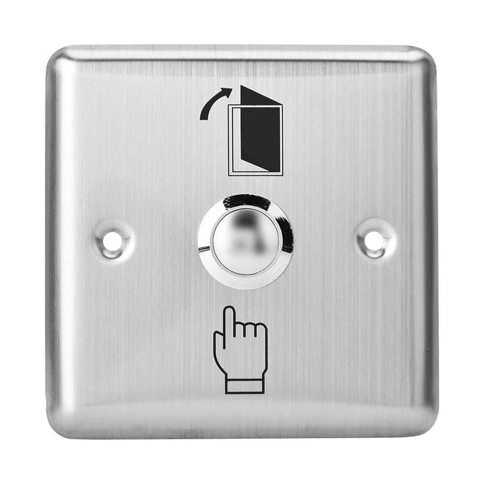
The exit button is a simple electronic component designed to terminate a process or exit a program. It is commonly used in user interfaces to close applications, return to a previous menu, or trigger a specific exit-related function. Exit buttons are typically momentary push-button switches that send a signal when pressed. They are widely used in embedded systems, industrial control panels, and access control systems.
Explore Projects Built with exit button


Explore Projects Built with exit button
Common Applications and Use Cases
- Access Control Systems: Used to unlock doors or deactivate security systems.
- Industrial Control Panels: Allows operators to stop a process or return to a safe state.
- Embedded Systems: Provides a user-friendly way to terminate a program or return to a main menu.
- Consumer Electronics: Used in devices like elevators, vending machines, and kiosks.
Technical Specifications
Below are the general technical specifications for a standard exit button. Note that specific models may vary slightly.
| Parameter | Value |
|---|---|
| Operating Voltage | 3.3V to 24V DC |
| Operating Current | 10mA to 500mA (depending on load) |
| Contact Type | Normally Open (NO) or Normally Closed (NC) |
| Button Type | Momentary Push Button |
| Material | Plastic or Metal |
| Mounting Style | Panel Mount or Surface Mount |
| Dimensions | Varies (e.g., 22mm diameter for panel mount) |
| LED Indicator (Optional) | 12V or 24V DC (if equipped) |
Pin Configuration and Descriptions
The exit button typically has two or three terminals, depending on its configuration:
| Pin | Label | Description |
|---|---|---|
| 1 | NO | Normally Open terminal. Connect to the circuit to close the connection when the button is pressed. |
| 2 | COM | Common terminal. Connect to the power source or ground, depending on the circuit design. |
| 3 | NC (Optional) | Normally Closed terminal. Connect to the circuit to open the connection when the button is pressed. |
Usage Instructions
How to Use the Exit Button in a Circuit
- Determine the Configuration: Identify whether the button is Normally Open (NO) or Normally Closed (NC). Most exit buttons are NO by default.
- Connect the Terminals:
- For a Normally Open button, connect the NO terminal to the input of the circuit and the COM terminal to the power source or ground.
- For a Normally Closed button, connect the NC terminal to the input of the circuit and the COM terminal to the power source or ground.
- Optional LED Indicator: If the button includes an LED, connect the LED terminals to the appropriate voltage (e.g., 12V or 24V DC) with a current-limiting resistor.
- Test the Button: Press the button to ensure it functions as expected, closing or opening the circuit.
Important Considerations and Best Practices
- Debouncing: Mechanical buttons can produce noise or "bouncing" when pressed. Use a hardware debouncing circuit (e.g., a capacitor) or software debouncing in microcontroller-based systems.
- Voltage and Current Ratings: Ensure the button's voltage and current ratings match your circuit requirements to avoid damage.
- Mounting: Securely mount the button to prevent accidental disconnection or damage during operation.
- LED Polarity: If the button includes an LED, ensure correct polarity when connecting to avoid damaging the LED.
Example: Connecting an Exit Button to an Arduino UNO
Below is an example of how to connect and use an exit button with an Arduino UNO. This example assumes a Normally Open button.
Circuit Diagram
- Connect the NO terminal of the button to Arduino digital pin 2.
- Connect the COM terminal to the ground (GND) pin of the Arduino.
- Use a pull-up resistor (10kΩ) between digital pin 2 and 5V to ensure a stable signal.
Arduino Code
// Define the pin connected to the exit button
const int buttonPin = 2;  // Exit button connected to digital pin 2
const int ledPin = 13;    // Built-in LED for feedback

void setup() {
  pinMode(buttonPin, INPUT_PULLUP); // Set button pin as input with internal pull-up
  pinMode(ledPin, OUTPUT);          // Set LED pin as output
  digitalWrite(ledPin, LOW);        // Turn off LED initially
}

void loop() {
  int buttonState = digitalRead(buttonPin); // Read the button state

  if (buttonState == LOW) { // Button pressed (LOW due to pull-up resistor)
    digitalWrite(ledPin, HIGH); // Turn on LED to indicate button press
    delay(500);                // Debounce delay
  } else {
    digitalWrite(ledPin, LOW);  // Turn off LED when button is not pressed
  }
}
Troubleshooting and FAQs
Common Issues and Solutions
Button Does Not Respond:
- Cause: Loose or incorrect wiring.
- Solution: Verify all connections and ensure the button terminals are properly connected.
LED Indicator Does Not Light Up:
- Cause: Incorrect polarity or missing current-limiting resistor.
- Solution: Check the LED connections and ensure a resistor is used to limit current.
Button Produces Erratic Behavior:
- Cause: Button bouncing.
- Solution: Add a hardware debouncing circuit (e.g., a capacitor) or implement software debouncing in your code.
Button Stuck or Difficult to Press:
- Cause: Physical damage or debris.
- Solution: Inspect the button for damage or debris and clean or replace it if necessary.
FAQs
Q: Can I use the exit button with AC circuits?
A: Most exit buttons are designed for DC circuits. If you need to use it with AC, ensure it is rated for the appropriate voltage and current.Q: How do I know if my button is Normally Open or Normally Closed?
A: Use a multimeter to test continuity. For a Normally Open button, continuity will only be present when the button is pressed.Q: Can I use the exit button for multiple functions?
A: Yes, you can use the button to trigger multiple actions in software by detecting the button press and executing the desired functions.
This concludes the documentation for the exit button.