
Cirkit Designer
Your all-in-one circuit design IDE
Home /
Component Documentation
How to Use EDGY: Examples, Pinouts, and Specs
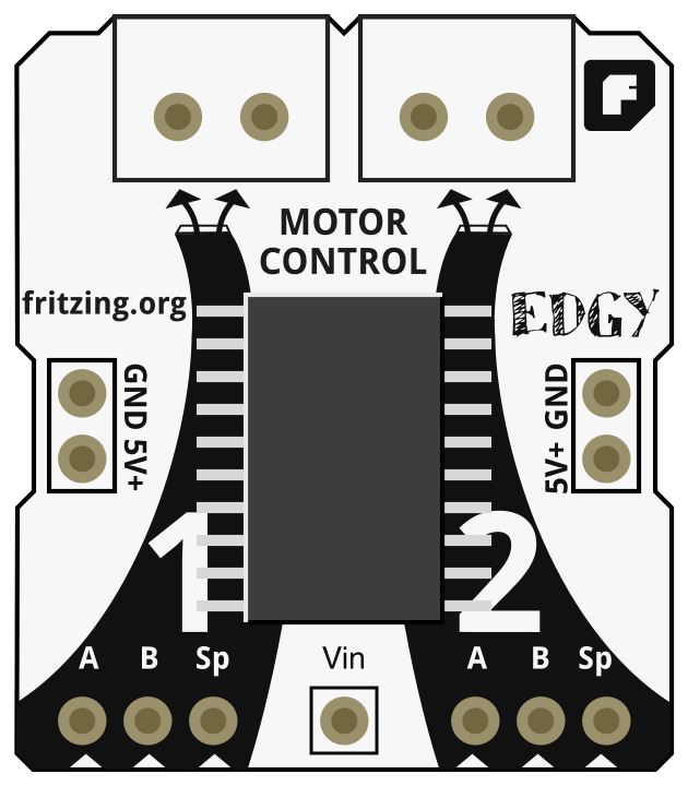
 Design with EDGY in Cirkit Designer
Introduction
- EDGY is a versatile electronic component designed to provide unique or unconventional functionality in electronic circuits. It is often associated with innovative or avant-garde designs, making it a popular choice for experimental and creative projects.
- Common applications include:
- Prototyping unconventional circuit designs
- Enhancing signal processing in creative audio or visual systems
- Adding unique behavior to robotics or IoT devices
- Supporting experimental research in electronics
Explore Projects Built with EDGY
ESP32-WROOM-32UE Wi-Fi Controlled Robotic Car with OLED Display and RGB LED
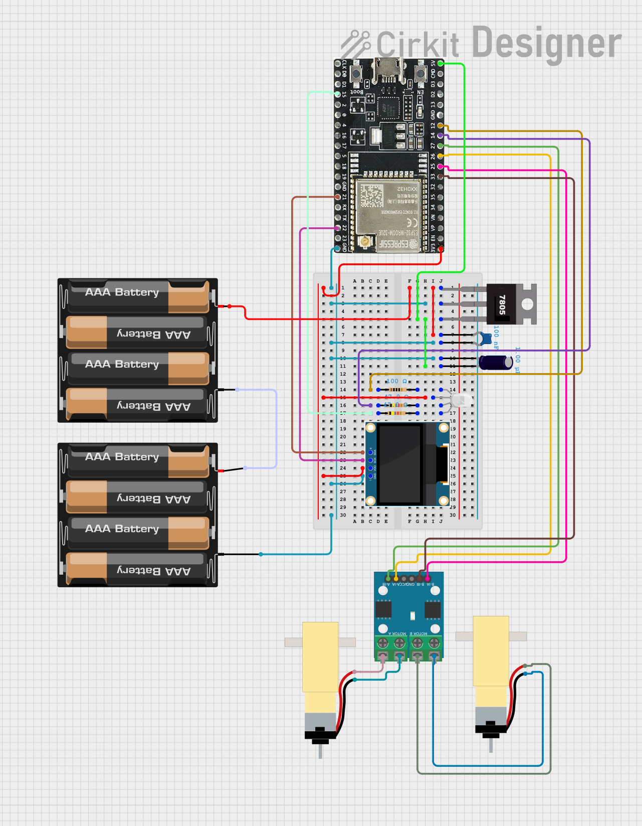
This circuit is a WiFi-controlled robotic system powered by an ESP32 microcontroller. It features an OLED display for status messages, an RGB LED for visual feedback, and dual hobby gearmotors driven by an L9110 motor driver for movement. The system is powered by a 4 x AAA battery pack regulated to 5V using a 7805 voltage regulator.
Open Project in Cirkit DesignerESP32-Based Smart Agriculture System with LoRa Communication
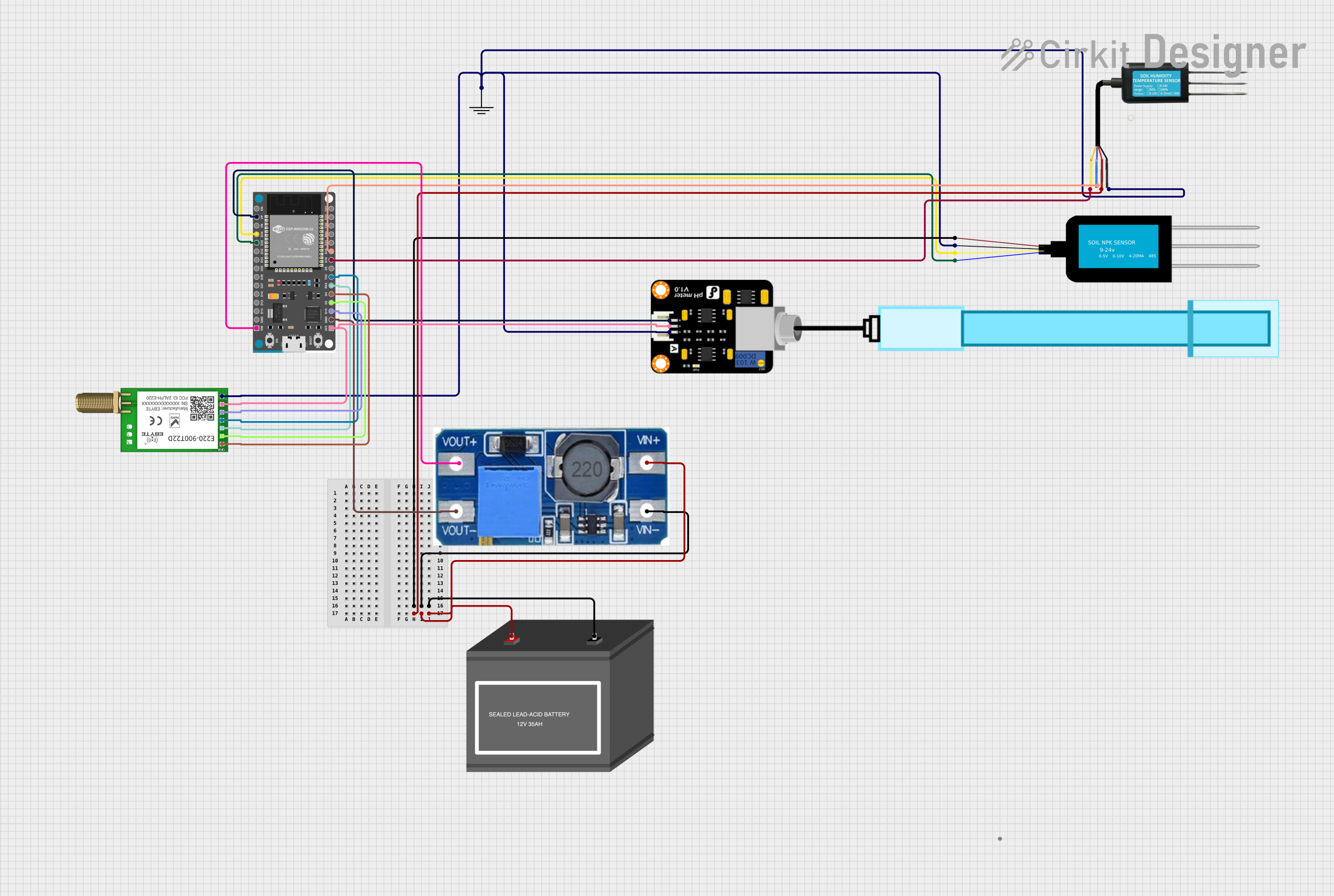
This circuit features an ESP32 Devkit V1 microcontroller as the central processing unit, interfacing with various sensors including a PH Meter, an NPK Soil Sensor, and a Soil Moisture Sensor for environmental data collection. It also includes an EBYTE LoRa E220 module for wireless communication. Power management is handled by a Step Up Boost Power Converter, which is connected to a 12V Battery, stepping up the voltage to power the ESP32 and sensors, with common ground connections throughout the circuit.
Open Project in Cirkit DesignerArduino Nano-Based ECG Data Logger with OLED Display and SD Card Storage
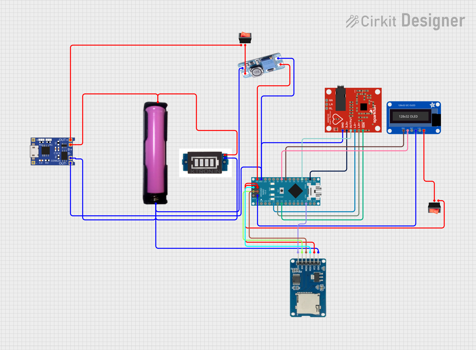
This circuit is designed for ECG data collection and display. It uses an AD8232 Heart Rate Monitor to capture heart signals, which are then processed by an Arduino Nano. The data is logged to a microSD card and can be visualized on an OLED display, with power management handled by a TP4056 charger module for a 18650 battery and a MT3608 boost converter to step up the voltage for the Arduino Nano.
Open Project in Cirkit DesignerBattery-Powered FPV Drone with Telemetry and Dual Motor Control
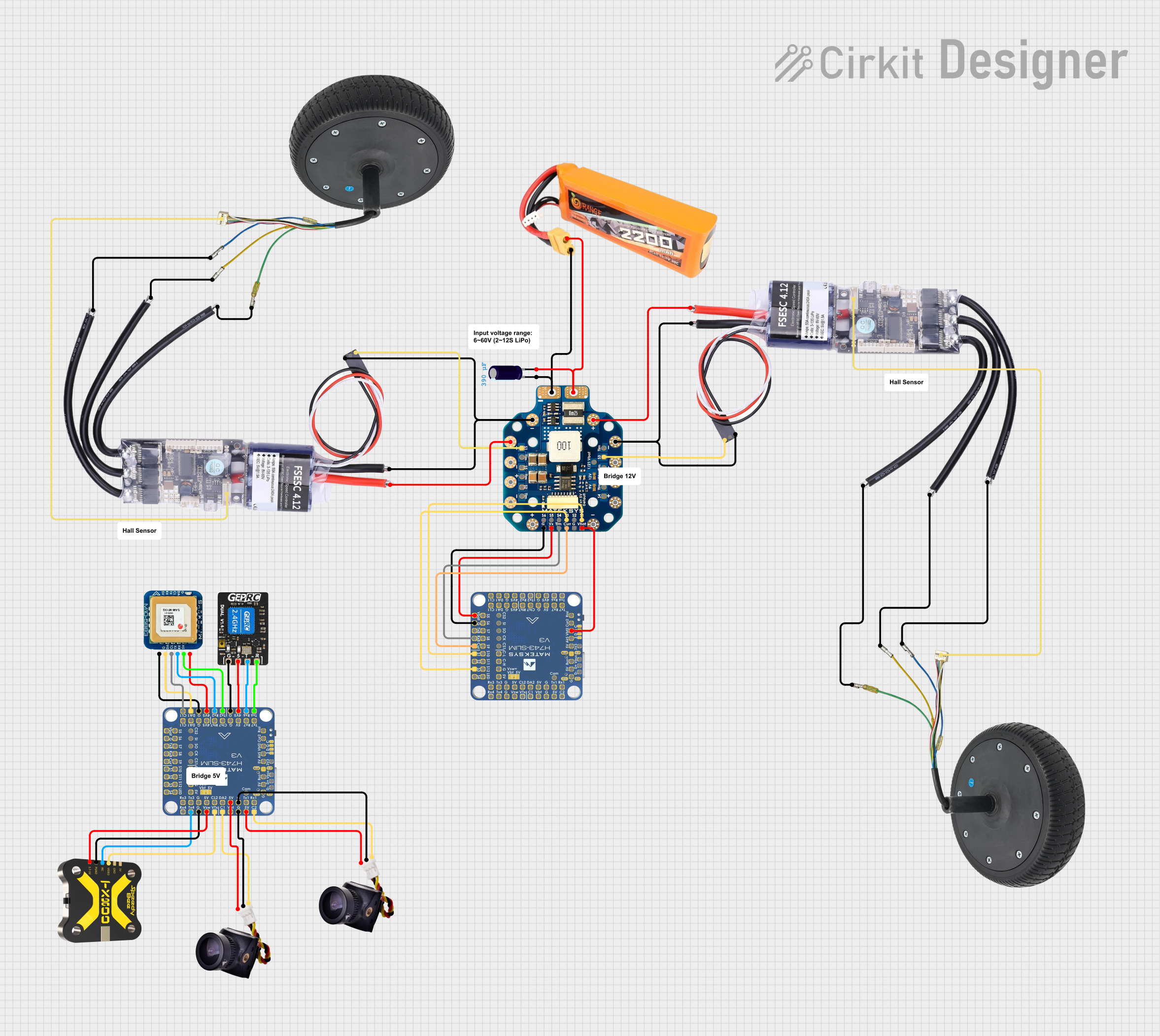
This circuit appears to be a power distribution and control system for a vehicle with two motorized wheels, possibly a drone or a robot. It includes a lipo battery connected to a Power Distribution Board (PDB) that distributes power to two Electronic Speed Controllers (ESCs) which in turn control the speed and direction of the motors. The system also integrates a flight controller (H743-SLIM V3) for managing various peripherals including GPS, FPV camera system, and a telemetry link (ExpressLRS).
Open Project in Cirkit DesignerExplore Projects Built with EDGY
ESP32-WROOM-32UE Wi-Fi Controlled Robotic Car with OLED Display and RGB LED
This circuit is a WiFi-controlled robotic system powered by an ESP32 microcontroller. It features an OLED display for status messages, an RGB LED for visual feedback, and dual hobby gearmotors driven by an L9110 motor driver for movement. The system is powered by a 4 x AAA battery pack regulated to 5V using a 7805 voltage regulator.
Open Project in Cirkit DesignerESP32-Based Smart Agriculture System with LoRa Communication
This circuit features an ESP32 Devkit V1 microcontroller as the central processing unit, interfacing with various sensors including a PH Meter, an NPK Soil Sensor, and a Soil Moisture Sensor for environmental data collection. It also includes an EBYTE LoRa E220 module for wireless communication. Power management is handled by a Step Up Boost Power Converter, which is connected to a 12V Battery, stepping up the voltage to power the ESP32 and sensors, with common ground connections throughout the circuit.
Open Project in Cirkit DesignerArduino Nano-Based ECG Data Logger with OLED Display and SD Card Storage
This circuit is designed for ECG data collection and display. It uses an AD8232 Heart Rate Monitor to capture heart signals, which are then processed by an Arduino Nano. The data is logged to a microSD card and can be visualized on an OLED display, with power management handled by a TP4056 charger module for a 18650 battery and a MT3608 boost converter to step up the voltage for the Arduino Nano.
Open Project in Cirkit DesignerBattery-Powered FPV Drone with Telemetry and Dual Motor Control
This circuit appears to be a power distribution and control system for a vehicle with two motorized wheels, possibly a drone or a robot. It includes a lipo battery connected to a Power Distribution Board (PDB) that distributes power to two Electronic Speed Controllers (ESCs) which in turn control the speed and direction of the motors. The system also integrates a flight controller (H743-SLIM V3) for managing various peripherals including GPS, FPV camera system, and a telemetry link (ExpressLRS).
Open Project in Cirkit DesignerTechnical Specifications
- Type: Multi-functional electronic component
- Operating Voltage: 3.3V to 5V
- Maximum Current: 50mA
- Power Dissipation: 250mW
- Operating Temperature: -40°C to 85°C
- Package Type: DIP-8 (Dual Inline Package with 8 pins)
Pin Configuration and Descriptions
| Pin Number | Pin Name | Description |
|---|---|---|
| 1 | VCC | Power supply input (3.3V to 5V) |
| 2 | GND | Ground connection |
| 3 | IN1 | Input signal 1 for primary functionality |
| 4 | IN2 | Input signal 2 for secondary functionality |
| 5 | OUT1 | Output signal 1 (processed signal from IN1) |
| 6 | OUT2 | Output signal 2 (processed signal from IN2) |
| 7 | MODE | Mode selection pin (LOW: Standard, HIGH: Custom) |
| 8 | NC | No connection (leave unconnected) |
Usage Instructions
Connecting the Component:
- Connect the VCC pin to a 3.3V or 5V power source.
- Connect the GND pin to the ground of your circuit.
- Provide input signals to IN1 and/or IN2 as required by your application.
- Use the MODE pin to select the desired operational mode:
- LOW: Standard functionality
- HIGH: Custom or experimental functionality
- The processed signals will be available at OUT1 and OUT2.
Important Considerations:
- Ensure the input signals do not exceed the operating voltage range (3.3V to 5V).
- Avoid exceeding the maximum current rating of 50mA to prevent damage.
- Use decoupling capacitors (e.g., 0.1µF) between VCC and GND to reduce noise.
- For unused pins (e.g., NC), leave them unconnected.
Example: Using EDGY with Arduino UNO: Below is an example of how to use the EDGY component with an Arduino UNO to process an input signal and output the result.
// Example: Using EDGY with Arduino UNO
const int IN1 = 2;  // Connect Arduino pin 2 to EDGY IN1
const int OUT1 = 3; // Connect Arduino pin 3 to EDGY OUT1
const int MODE = 4; // Connect Arduino pin 4 to EDGY MODE

void setup() {
  pinMode(IN1, OUTPUT);  // Set IN1 as output to send signal
  pinMode(OUT1, INPUT);  // Set OUT1 as input to read processed signal
  pinMode(MODE, OUTPUT); // Set MODE as output to control functionality

  digitalWrite(MODE, LOW); // Set EDGY to Standard mode
}

void loop() {
  digitalWrite(IN1, HIGH); // Send a HIGH signal to EDGY IN1
  delay(1000);             // Wait for 1 second
  digitalWrite(IN1, LOW);  // Send a LOW signal to EDGY IN1
  delay(1000);             // Wait for 1 second

  // Read the processed signal from EDGY OUT1
  int processedSignal = digitalRead(OUT1);
  if (processedSignal == HIGH) {
    // Perform an action if the processed signal is HIGH
  }
}
Troubleshooting and FAQs
Common Issues
No Output Signal:
- Ensure the VCC and GND pins are properly connected.
- Verify that the input signals are within the operating voltage range.
- Check the MODE pin configuration (LOW for Standard, HIGH for Custom).
Component Overheating:
- Ensure the current does not exceed 50mA.
- Verify that the power dissipation is within the 250mW limit.
Unstable Output:
- Add decoupling capacitors between VCC and GND to reduce noise.
- Ensure proper grounding in the circuit.
FAQs
Can I use EDGY with a 12V power supply?
- No, EDGY operates within a voltage range of 3.3V to 5V. Using a 12V supply may damage the component.
What happens if I leave the MODE pin unconnected?
- The behavior of the component may be unpredictable. It is recommended to explicitly set the MODE pin to either LOW or HIGH.
Can EDGY process analog signals?
- EDGY is primarily designed for digital signals. For analog signal processing, additional circuitry may be required.
Is EDGY compatible with other microcontrollers besides Arduino?
- Yes, EDGY can be used with any microcontroller that operates within its voltage and current specifications.