Cirkit Designer Logo
Cirkit Designer
Your all-in-one circuit design IDE
Home / 
Component Documentation

How to Use DS18B20: Examples, Pinouts, and Specs

Image of DS18B20
Cirkit Designer LogoDesign with DS18B20 in Cirkit Designer

Introduction

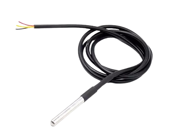
The DS18B20 is a precision digital temperature sensor that provides 9-bit to 12-bit Celsius temperature measurements. It communicates over a 1-Wire bus that by design requires only one data line (and ground) for communication with a central microprocessor. It has an operating temperature range of -55°C to +125°C and is accurate to ±0.5°C in the range of -10°C to +85°C. Additionally, the DS18B20 can derive power directly from the data line ("parasite power"), eliminating the need for an external power supply.

Common applications of the DS18B20 include HVAC environmental controls, temperature monitoring systems inside buildings, equipment or machinery, and process monitoring and control systems.

Explore Projects Built with DS18B20

Use Cirkit Designer to design, explore, and prototype these projects online. Some projects support real-time simulation. Click "Open Project" to start designing instantly!
Arduino UNO Based Temperature Monitoring System with DS18B20 Sensor
Image of DS18b20 sim test: A project utilizing DS18B20 in a practical application
This circuit is designed to measure temperature using a DS18B20 sensor interfaced with an Arduino UNO. The Arduino reads temperature data from the sensor via a 1-Wire bus with a pull-up resistor and outputs the readings to the serial console.
Cirkit Designer LogoOpen Project in Cirkit Designer
Arduino UNO-Based Multi-Sensor Environmental Monitoring System
Image of diagrama tesis: A project utilizing DS18B20 in a practical application
This circuit involves an Arduino UNO microcontroller interfacing with a DS18B20 temperature sensor. The sensor is powered by the Arduino's 5V and GND pins, and its data pin is connected to a digital I/O pin on the Arduino, with a pull-up resistor in place. The setup is designed to read temperature data from the sensor.
Cirkit Designer LogoOpen Project in Cirkit Designer
ESP8266 NodeMCU with DS18B20 Temperature Sensor Monitoring
Image of SUHU: A project utilizing DS18B20 in a practical application
This circuit features an ESP8266 NodeMCU microcontroller connected to a DS18B20 temperature sensor. The sensor's data line (DQ) is connected to the D2 pin of the NodeMCU through a 4.7k ohm pull-up resistor, which is a common configuration for one-wire temperature sensors. The sensor is powered by the 3.3V supply from the NodeMCU, and both the sensor and the NodeMCU share a common ground.
Cirkit Designer LogoOpen Project in Cirkit Designer
Arduino UNO with Multiple DS18B20 Sensors for Temperature Monitoring
Image of Interfacing Multiple DS18B20 Digital Temperature Sensors With Arduino UNO: A project utilizing DS18B20 in a practical application
This circuit is designed to monitor temperatures using multiple DS18B20 1-Wire temperature sensors connected to an Arduino UNO microcontroller. The sensors are powered by the Arduino's 5V output and share a common data line (DQ) connected to digital pin 2 through a 4.7kΩ pull-up resistor, allowing for simultaneous temperature readings. The Arduino runs a sketch that reads temperatures from each sensor and outputs the readings to the serial monitor in both Celsius and Fahrenheit.
Cirkit Designer LogoOpen Project in Cirkit Designer

Explore Projects Built with DS18B20

Use Cirkit Designer to design, explore, and prototype these projects online. Some projects support real-time simulation. Click "Open Project" to start designing instantly!
Image of DS18b20 sim test: A project utilizing DS18B20 in a practical application
Arduino UNO Based Temperature Monitoring System with DS18B20 Sensor
This circuit is designed to measure temperature using a DS18B20 sensor interfaced with an Arduino UNO. The Arduino reads temperature data from the sensor via a 1-Wire bus with a pull-up resistor and outputs the readings to the serial console.
Cirkit Designer LogoOpen Project in Cirkit Designer
Image of diagrama tesis: A project utilizing DS18B20 in a practical application
Arduino UNO-Based Multi-Sensor Environmental Monitoring System
This circuit involves an Arduino UNO microcontroller interfacing with a DS18B20 temperature sensor. The sensor is powered by the Arduino's 5V and GND pins, and its data pin is connected to a digital I/O pin on the Arduino, with a pull-up resistor in place. The setup is designed to read temperature data from the sensor.
Cirkit Designer LogoOpen Project in Cirkit Designer
Image of SUHU: A project utilizing DS18B20 in a practical application
ESP8266 NodeMCU with DS18B20 Temperature Sensor Monitoring
This circuit features an ESP8266 NodeMCU microcontroller connected to a DS18B20 temperature sensor. The sensor's data line (DQ) is connected to the D2 pin of the NodeMCU through a 4.7k ohm pull-up resistor, which is a common configuration for one-wire temperature sensors. The sensor is powered by the 3.3V supply from the NodeMCU, and both the sensor and the NodeMCU share a common ground.
Cirkit Designer LogoOpen Project in Cirkit Designer
Image of Interfacing Multiple DS18B20 Digital Temperature Sensors With Arduino UNO: A project utilizing DS18B20 in a practical application
Arduino UNO with Multiple DS18B20 Sensors for Temperature Monitoring
This circuit is designed to monitor temperatures using multiple DS18B20 1-Wire temperature sensors connected to an Arduino UNO microcontroller. The sensors are powered by the Arduino's 5V output and share a common data line (DQ) connected to digital pin 2 through a 4.7kΩ pull-up resistor, allowing for simultaneous temperature readings. The Arduino runs a sketch that reads temperatures from each sensor and outputs the readings to the serial monitor in both Celsius and Fahrenheit.
Cirkit Designer LogoOpen Project in Cirkit Designer

Technical Specifications

Key Technical Details

  • Supply Voltage (VDD): 3.0V to 5.5V
  • Operating Temperature Range: -55°C to +125°C
  • Accuracy: ±0.5°C from -10°C to +85°C
  • Resolution: Selectable from 9 to 12 bits
  • Unique 64-bit Serial Code: Stored in an onboard ROM
  • Conversion Time: 750ms at 12-bit resolution

Pin Configuration and Descriptions

Pin Number Name Description
1 GND Ground
2 DQ Data Line
3 VDD Power Supply (3.0V to 5.5V)

Usage Instructions

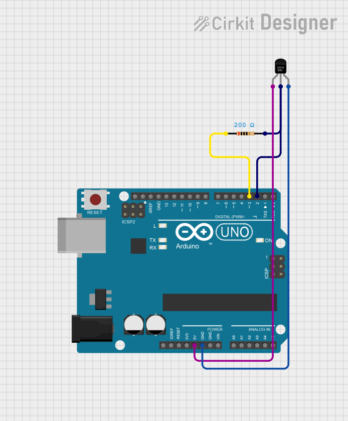
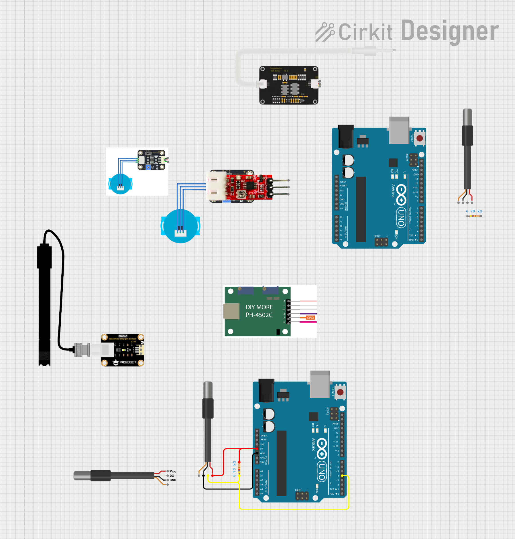
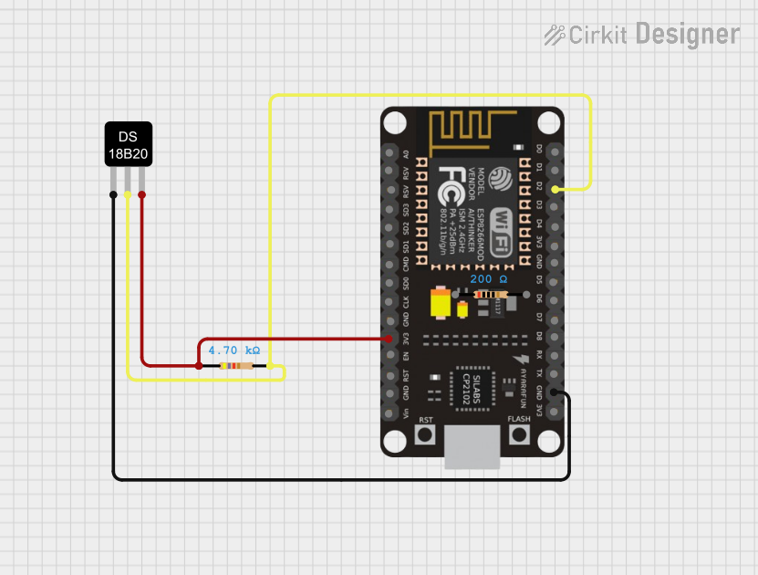
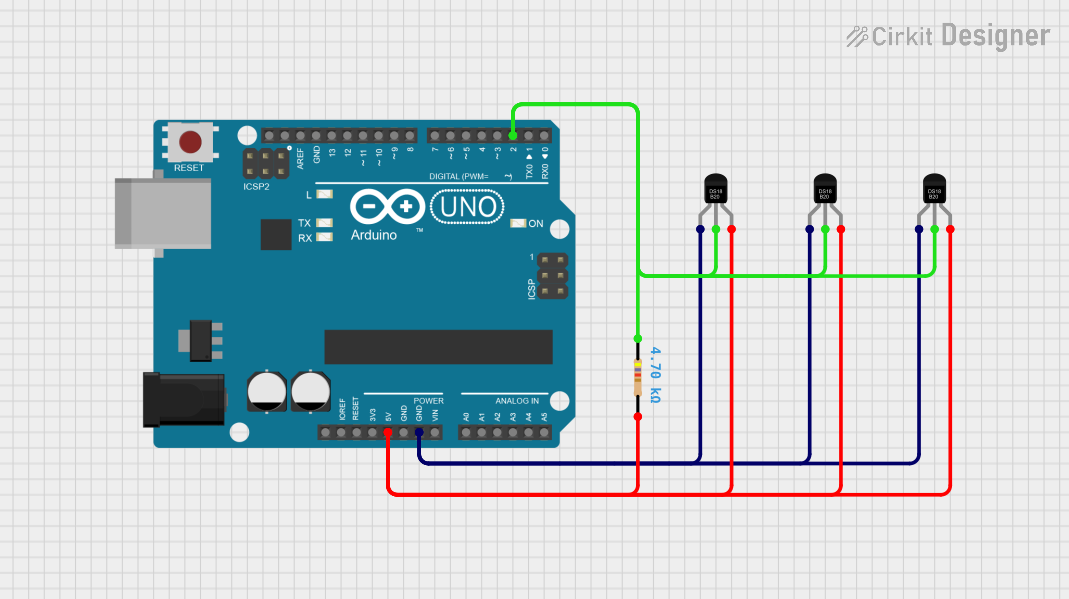
Connecting the DS18B20 to a Circuit

  1. Connect the GND pin to the ground of the power supply.
  2. Connect the VDD pin to the positive side of the power supply (3.0V to 5.5V).
  3. Connect the DQ pin to the GPIO pin on the microcontroller.
  4. A 4.7kΩ resistor is typically used as a pull-up on the DQ line to VDD.

Important Considerations and Best Practices

  • Ensure that the power supply is within the specified range (3.0V to 5.5V).
  • Use a pull-up resistor on the DQ line to prevent data corruption.
  • For long wire runs or multiple sensors, consider using a lower value pull-up resistor.
  • Avoid placing the sensor near heat-generating components to prevent false readings.
  • When using parasite power, the VDD pin should be connected to ground.

Example Code for Arduino UNO

#include <OneWire.h>
#include <DallasTemperature.h>

// Data wire is connected to Arduino digital pin 2
#define ONE_WIRE_BUS 2

// Setup a oneWire instance to communicate with any OneWire device
OneWire oneWire(ONE_WIRE_BUS);

// Pass oneWire reference to DallasTemperature library
DallasTemperature sensors(&oneWire);

void setup() {
  Serial.begin(9600);
  sensors.begin(); // Start up the library
}

void loop() {
  sensors.requestTemperatures(); // Send command to get temperatures
  Serial.print("Temperature is: ");
  Serial.print(sensors.getTempCByIndex(0)); // Get temperature in Celsius
  Serial.println("°C");
  delay(1000); // Wait 1 second before next reading
}

Troubleshooting and FAQs

Common Issues

  • Temperature Readings Are Inaccurate:
    • Ensure the sensor is not placed near heat sources.
    • Check the pull-up resistor value; it may need adjustment.
  • No Data or Communication Errors:
    • Verify connections and ensure the pull-up resistor is in place.
    • Check if the correct GPIO pin is defined in the code.
  • Multiple Sensors Not Working:
    • Ensure each sensor has a unique address.
    • Use a star topology for wiring multiple sensors to reduce signal degradation.

Solutions and Tips for Troubleshooting

  • Double-check wiring, especially the pull-up resistor on the DQ line.
  • Use the sensors.getAddress() function to verify the unique address of each DS18B20 sensor.
  • For long cable runs, use shielded cable to minimize interference.
  • If using parasite power, ensure that the VDD pin is correctly connected to ground.

FAQs

Q: Can I connect multiple DS18B20 sensors to the same data line? A: Yes, each DS18B20 has a unique 64-bit serial code, which allows multiple sensors to function on the same 1-Wire bus.

Q: How do I set the resolution of the DS18B20? A: The resolution can be set using the sensors.setResolution() function in the DallasTemperature library.

Q: What is the maximum cable length for the DS18B20? A: The maximum cable length depends on several factors, including the quality of the cable and the pull-up resistor value. Generally, lengths up to 100 meters are possible with careful design.

Q: Is it necessary to use an external power supply for the DS18B20? A: No, the DS18B20 can operate in parasite power mode, where it draws power from the data line. However, an external power supply can be used if preferred.