How to Use LM2956 Buck Converter DC-DC: Examples, Pinouts, and Specs
Introduction
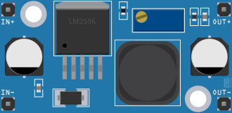
The LM2956 Buck Converter DC-DC is a highly efficient voltage step-down integrated circuit designed by ElectronicsComponents. It is commonly used in applications where a lower DC voltage is required from a higher DC voltage source. Typical use cases include battery-powered devices, power supplies, and embedded systems where power efficiency is crucial.
Explore Projects Built with LM2956 Buck Converter DC-DC


Explore Projects Built with LM2956 Buck Converter DC-DC
Technical Specifications
Key Technical Details
- Input Voltage (Vin): 4.5V to 28V
- Output Voltage (Vout): 1.23V to 20V (Adjustable)
- Output Current: Up to 3A (with proper heat sinking)
- Switching Frequency: 150 kHz
- Efficiency: Up to 92% (depends on input and output voltage, load current, and temperature)
- Operating Temperature: -40°C to +125°C
Pin Configuration and Descriptions
| Pin Number | Pin Name | Description |
|---|---|---|
| 1 | GND | Ground reference for the circuit. |
| 2 | Vin | Input voltage to the buck converter. |
| 3 | Vout | Regulated output voltage from the buck converter. |
| 4 | Feedback | Feedback pin for output voltage regulation. |
| 5 | ON/OFF | Enables or disables the output when driven high or low, respectively. |
Usage Instructions
How to Use the Component in a Circuit
- Input Supply: Connect a DC voltage source between the Vin and GND pins. Ensure that the source voltage is within the specified input range.
- Output Voltage Setting: To set the desired output voltage, connect a resistor divider from Vout to Feedback to GND. The output voltage can be calculated using the formula:
Vout = 1.23V * (1 + R1/R2), where R1 is connected between Vout and Feedback, and R2 is between Feedback and GND. - Load Connection: Connect your load to the Vout and GND pins.
- ON/OFF Control (Optional): If you wish to control the output of the buck converter, connect a switch or logic signal to the ON/OFF pin.
Important Considerations and Best Practices
- Heat Dissipation: Ensure adequate heat sinking for the LM2956 when drawing high currents, as power dissipation can lead to increased temperatures.
- Capacitor Selection: Use high-quality capacitors at the input and output for stability. Typically, low ESR capacitors are recommended.
- Inductor Selection: Choose an inductor that can handle the peak current without saturation and with minimal losses.
- PCB Layout: Keep the switch node (SW) trace short and away from sensitive analog areas to minimize noise and EMI.
Troubleshooting and FAQs
Common Issues
- Output Voltage is Too High or Low: Check the resistor divider values and ensure they are within tolerance. Also, verify the feedback connection.
- Converter is Overheating: Ensure that the input voltage is within the specified range and that the load current does not exceed the maximum rating. Improve heat sinking or airflow if necessary.
- Output is Unstable: Verify the quality and placement of the input and output capacitors. Check the inductor for saturation or signs of damage.
Solutions and Tips for Troubleshooting
- No Output Voltage: Ensure that the ON/OFF pin is set high if used. Check all connections and solder joints for continuity.
- Noise Issues: If noise is a concern, add a snubber circuit across the switch node or improve the PCB layout to minimize loop areas.
FAQs
Q: Can I use the LM2956 without an external switch for the ON/OFF pin? A: Yes, the ON/OFF pin can be left floating or permanently connected to Vin if you do not require the enable/disable feature.
Q: What is the maximum output current of the LM2956? A: The LM2956 can deliver up to 3A of output current with proper heat sinking.
Q: How do I calculate the correct inductor value for my application? A: The inductor value depends on the input and output voltages, desired ripple current, and switching frequency. Use the datasheet guidelines and design tools provided by ElectronicsComponents for accurate selection.
Example Code for Arduino UNO
// This example demonstrates how to control the LM2956 ON/OFF pin using an Arduino UNO.

const int onOffPin = 7; // Connect the ON/OFF pin of LM2956 to digital pin 7 on Arduino

void setup() {
  pinMode(onOffPin, OUTPUT); // Set the ON/OFF pin as an output
  digitalWrite(onOffPin, HIGH); // Enable the LM2956 output
}

void loop() {
  // The LM2956 output can be toggled on and off as needed
  digitalWrite(onOffPin, LOW); // Disable the LM2956 output
  delay(1000); // Wait for 1 second
  digitalWrite(onOffPin, HIGH); // Enable the LM2956 output
  delay(1000); // Wait for 1 second
}
Note: This code is for demonstration purposes only. Ensure that the rest of your circuit is correctly set up before connecting it to an Arduino.