
How to Use TCRT 5000 IR SENSOR schematic: Examples, Pinouts, and Specs
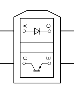
 Design with TCRT 5000 IR SENSOR schematic in Cirkit Designer
Introduction
The TCRT 5000 is an infrared (IR) sensor module that integrates an IR emitter and a phototransistor in a single package. It is designed for detecting objects and measuring proximity by sensing the intensity of reflected IR light. The sensor is widely used in applications such as line-following robots, object detection, and proximity sensing in automation systems.
Explore Projects Built with TCRT 5000 IR SENSOR schematic
 Open Project in Cirkit Designer
 Open Project in Cirkit Designer
 Open Project in Cirkit Designer
 Open Project in Cirkit Designer
Explore Projects Built with TCRT 5000 IR SENSOR schematic
Open Project in Cirkit DesignerOpen Project in Cirkit DesignerOpen Project in Cirkit DesignerOpen Project in Cirkit DesignerCommon Applications:
- Line-following robots
- Obstacle detection in robotics
- Proximity sensing in industrial automation
- Position encoders
- Reflective optical switches
Technical Specifications
Key Technical Details:
- Operating Voltage: 3.3V to 5V
- Current Consumption: ~10mA (typical)
- IR Wavelength: 950nm
- Detection Range: 2mm to 15mm (depending on object reflectivity)
- Output Type: Analog or digital (depending on circuit design)
- Operating Temperature: -25°C to +85°C
- Package Type: Through-hole
Pin Configuration and Descriptions:
The TCRT 5000 sensor has four pins. Below is the pinout and description:
| Pin Number | Pin Name | Description |
|---|---|---|
| 1 | Emitter (A) | Anode of the IR LED (connect to positive voltage) |
| 2 | Emitter (K) | Cathode of the IR LED (connect to ground) |
| 3 | Collector | Collector of the phototransistor (output signal) |
| 4 | Emitter | Emitter of the phototransistor (connect to ground) |
Usage Instructions
How to Use the TCRT 5000 in a Circuit:
- Powering the Sensor: Connect the IR LED anode (Pin 1) to a positive voltage (3.3V or 5V) through a current-limiting resistor (typically 220Ω to 330Ω). Connect the cathode (Pin 2) to ground.
- Phototransistor Output: Connect the phototransistor's collector (Pin 3) to a pull-up resistor (e.g., 10kΩ) and then to the positive voltage. The emitter (Pin 4) should be connected to ground.
- Signal Reading: The voltage at the collector (Pin 3) will vary depending on the intensity of the reflected IR light. A higher reflection results in a lower voltage at the output.
Important Considerations:
- Object Reflectivity: The sensor's performance depends on the reflectivity of the object. Light-colored or shiny surfaces reflect more IR light, while dark or matte surfaces reflect less.
- Ambient Light Interference: Avoid using the sensor in environments with strong ambient IR light (e.g., sunlight) to minimize interference.
- Distance Calibration: Adjust the distance between the sensor and the object for optimal detection. The detection range is typically 2mm to 15mm.
Example: Connecting the TCRT 5000 to an Arduino UNO
Below is an example of how to connect and use the TCRT 5000 with an Arduino UNO to detect objects:
Circuit Connections:
- TCRT 5000 Pin 1 (Emitter A): Connect to Arduino 5V through a 220Ω resistor.
- TCRT 5000 Pin 2 (Emitter K): Connect to Arduino GND.
- TCRT 5000 Pin 3 (Collector): Connect to Arduino analog pin A0 with a 10kΩ pull-up resistor to 5V.
- TCRT 5000 Pin 4 (Emitter): Connect to Arduino GND.
Arduino Code:
// TCRT 5000 IR Sensor Example Code
// Reads the analog signal from the sensor and prints it to the Serial Monitor.

const int sensorPin = A0; // Analog pin connected to the sensor's output

void setup() {
  Serial.begin(9600); // Initialize serial communication at 9600 baud
}

void loop() {
  int sensorValue = analogRead(sensorPin); // Read the analog value from the sensor
  Serial.print("Sensor Value: ");
  Serial.println(sensorValue); // Print the sensor value to the Serial Monitor

  delay(100); // Delay for 100ms before the next reading
}
Best Practices:
- Use a decoupling capacitor (e.g., 0.1µF) across the power supply pins to reduce noise.
- Place the sensor close to the object for accurate detection.
- Shield the sensor from external IR sources to improve reliability.
Troubleshooting and FAQs
Common Issues and Solutions:
No Output Signal:
- Check the connections and ensure the IR LED is powered correctly.
- Verify the pull-up resistor on the phototransistor's collector pin.
Inconsistent Readings:
- Ensure the object is within the sensor's detection range.
- Reduce ambient IR light interference by shielding the sensor.
Low Sensitivity:
- Increase the current through the IR LED by reducing the value of the current-limiting resistor (but do not exceed the LED's maximum current rating).
- Ensure the object has a reflective surface.
Output Always High or Low:
- Verify the pull-up resistor value (10kΩ is typical).
- Check for proper grounding of the phototransistor emitter pin.
FAQs:
Q: Can the TCRT 5000 detect black surfaces?
A: Black surfaces absorb most IR light, making detection difficult. Use reflective or light-colored surfaces for better results.
Q: What is the maximum detection range of the TCRT 5000?
A: The sensor can detect objects up to 15mm away, depending on the object's reflectivity.
Q: Can I use the TCRT 5000 with a 3.3V system?
A: Yes, the sensor operates at 3.3V, but ensure the current-limiting resistor for the IR LED is appropriately calculated.
Q: How do I reduce interference from ambient light?
A: Use the sensor in a controlled environment or add an IR filter to block unwanted wavelengths.
By following this documentation, you can effectively integrate the TCRT 5000 IR sensor into your projects for reliable object detection and proximity sensing.