How to Use NEO 6M GPS module: Examples, Pinouts, and Specs
Introduction
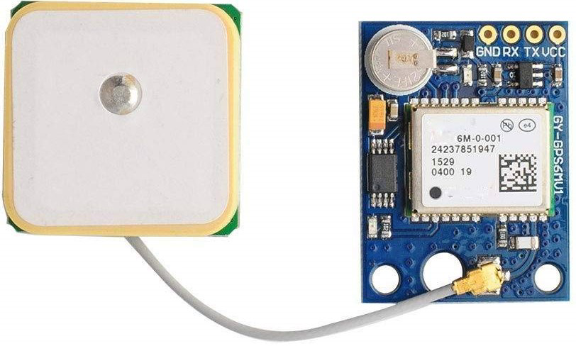
The NEO 6M GPS module is a compact and high-performance GPS receiver designed to provide accurate positioning data. It features a built-in ceramic antenna for reliable signal reception and supports multiple satellite systems, including GPS, GLONASS, and SBAS. This module is widely used in applications such as robotics, drones, vehicle tracking, and navigation systems due to its ease of integration and reliable performance.
The NEO 6M is capable of delivering real-time location data with high precision, making it an essential component for projects requiring geolocation functionality. Its small form factor and low power consumption make it suitable for portable and battery-powered devices.
Explore Projects Built with NEO 6M GPS module

Explore Projects Built with NEO 6M GPS module
Technical Specifications
- Model: NEO 6M GPS Module
- Input Voltage: 3.3V to 5V
- Operating Current: 45mA (typical)
- Communication Protocol: UART (default baud rate: 9600 bps)
- Positioning Accuracy: 2.5 meters (CEP)
- Update Rate: 1 Hz (default), configurable up to 5 Hz
- Antenna: Built-in ceramic antenna (external antenna supported via u.FL connector)
- Backup Battery: CR1220 coin cell for maintaining GPS data (optional)
- Operating Temperature: -40°C to +85°C
- Dimensions: 25mm x 35mm x 6mm
Pin Configuration and Descriptions
The NEO 6M GPS module typically has a 4-pin interface. The pinout is as follows:
| Pin | Name | Description |
|---|---|---|
| 1 | VCC | Power input (3.3V to 5V) |
| 2 | GND | Ground |
| 3 | TX | UART Transmit (data output from module) |
| 4 | RX | UART Receive (data input to module) |
Usage Instructions
How to Use the NEO 6M GPS Module in a Circuit
- Power the Module: Connect the VCC pin to a 3.3V or 5V power source and the GND pin to the ground of your circuit.
- Connect UART Pins:
- Connect the TX pin of the module to the RX pin of your microcontroller (e.g., Arduino UNO).
- Connect the RX pin of the module to the TX pin of your microcontroller.
- Backup Battery (Optional): Insert a CR1220 coin cell battery into the module's battery holder to retain GPS data during power loss.
- Antenna Placement: Ensure the built-in antenna has a clear view of the sky for optimal satellite reception. If needed, connect an external antenna via the u.FL connector.
Important Considerations and Best Practices
- Baud Rate: The default UART baud rate is 9600 bps. Ensure your microcontroller is configured to communicate at this rate.
- Signal Reception: For best results, use the module outdoors or near a window to ensure a clear line of sight to satellites.
- Cold Start vs. Warm Start: A cold start (first-time satellite acquisition) may take up to 30 seconds, while a warm start (with backup battery) is faster.
- Voltage Levels: If using a 3.3V microcontroller, ensure the TX pin of the GPS module is compatible with 3.3V logic levels.
Example: Connecting to an Arduino UNO
Below is an example of how to use the NEO 6M GPS module with an Arduino UNO to read GPS data.
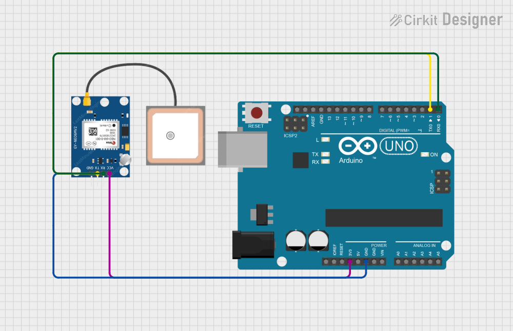
Circuit Diagram
- VCC → 5V on Arduino
- GND → GND on Arduino
- TX → Pin 4 on Arduino
- RX → Pin 3 on Arduino (via a voltage divider if using 5V logic)
Arduino Code
#include <SoftwareSerial.h>

// Create a SoftwareSerial instance for communication with the GPS module
SoftwareSerial gpsSerial(4, 3); // RX = Pin 4, TX = Pin 3

void setup() {
  Serial.begin(9600); // Initialize Serial Monitor at 9600 bps
  gpsSerial.begin(9600); // Initialize GPS module communication at 9600 bps

  Serial.println("NEO 6M GPS Module Test");
  Serial.println("Waiting for GPS data...");
}

void loop() {
  // Check if data is available from the GPS module
  while (gpsSerial.available()) {
    char c = gpsSerial.read(); // Read one character from the GPS module
    Serial.print(c); // Print the character to the Serial Monitor

    // Note: GPS data is in NMEA format. Use a library like TinyGPS++ to parse it.
  }
}
Notes:
- The above code outputs raw NMEA sentences from the GPS module to the Serial Monitor.
- For parsing and extracting useful data (e.g., latitude, longitude), consider using the TinyGPS++ library.
Troubleshooting and FAQs
Common Issues and Solutions
No GPS Data Received:
- Ensure the module is powered correctly (check VCC and GND connections).
- Verify the TX and RX connections between the module and microcontroller.
- Confirm the baud rate is set to 9600 bps in your code.
Poor Satellite Signal:
- Place the module outdoors or near a window for better signal reception.
- Avoid obstructions like walls, roofs, or metal objects that block satellite signals.
Long Time to Acquire Signal:
- This is normal during a cold start. Use a backup battery to enable faster warm starts.
- Ensure the module has a clear view of the sky.
Data Corruption or Incomplete NMEA Sentences:
- Check for loose or incorrect wiring.
- Ensure the microcontroller's UART buffer is not overflowing.
FAQs
Q: Can I use the NEO 6M GPS module with a 3.3V microcontroller?
A: Yes, the module supports 3.3V logic levels. However, ensure the RX pin of the module does not receive voltages higher than 3.3V.Q: How do I parse NMEA sentences?
A: Use libraries like TinyGPS++ or Adafruit GPS to parse and extract data such as latitude, longitude, and time.Q: Can I increase the update rate?
A: Yes, the update rate can be configured up to 5 Hz using specific NMEA commands. Refer to the module's datasheet for details.Q: What is the purpose of the backup battery?
A: The backup battery retains satellite data, enabling faster warm starts after power loss.
By following this documentation, you can effectively integrate and use the NEO 6M GPS module in your projects.