How to Use DTMF MT8870: Examples, Pinouts, and Specs
Introduction
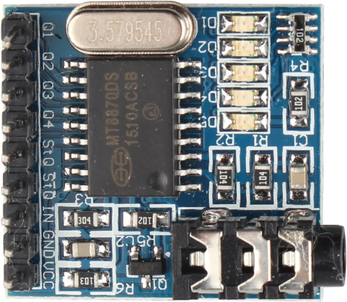
The MT8870 is a Dual-Tone Multi-Frequency (DTMF) decoder manufactured by HALJIA with the part ID MT8870DS. It is designed to decode DTMF signals, which are commonly generated by telephone keypads, into a binary-coded decimal (BCD) output. This component is widely used in telecommunication systems, remote control applications, and embedded systems to interpret keypad inputs.
Explore Projects Built with DTMF MT8870


Explore Projects Built with DTMF MT8870
Common Applications
- Telephone systems for decoding keypad inputs
- Remote control systems
- Security systems for access control
- Embedded systems requiring DTMF signal decoding
- Robotics for remote operation via DTMF signals
Technical Specifications
Key Technical Details
- Operating Voltage: 2.5V to 5.5V
- Operating Current: 3mA (typical)
- Input Signal Frequency: 697Hz to 1633Hz (standard DTMF frequencies)
- Output Format: 4-bit binary-coded decimal (BCD)
- Input Impedance: 100kΩ (typical)
- Operating Temperature Range: -40°C to +85°C
- Package Type: 18-pin DIP or SOIC
Pin Configuration and Descriptions
The MT8870 has 18 pins, each with a specific function. The table below provides a detailed description of each pin:
| Pin Number | Pin Name | Description |
|---|---|---|
| 1 | IN+ | Non-inverting input for the analog signal (DTMF signal input). |
| 2 | IN- | Inverting input for the analog signal (used for differential input). |
| 3 | GS | Gain select pin for the input amplifier. |
| 4 | VREF | Reference voltage output (typically 2.5V). |
| 5 | INH | Inhibit pin. When high, it disables the detection of DTMF signals. |
| 6 | PWDN | Power-down mode. When high, the chip enters low-power mode. |
| 7 | OSC1 | Oscillator input. Connect to an external crystal or clock source. |
| 8 | OSC2 | Oscillator output. Connect to an external crystal or leave unconnected. |
| 9 | VSS | Ground (0V). |
| 10 | Q4 | BCD output bit 4 (most significant bit). |
| 11 | Q3 | BCD output bit 3. |
| 12 | Q2 | BCD output bit 2. |
| 13 | Q1 | BCD output bit 1 (least significant bit). |
| 14 | STD | Delayed steering output. Indicates when a valid DTMF signal is detected. |
| 15 | TOE | Three-state output enable. Controls the state of the BCD output pins. |
| 16 | VDD | Positive power supply (2.5V to 5.5V). |
| 17 | StD | Steering output. Goes high when a valid DTMF signal is detected. |
| 18 | EST | Early steering output. Indicates the presence of a DTMF signal. |
Usage Instructions
How to Use the MT8870 in a Circuit
- Power Supply: Connect the VDD pin to a 5V power supply and the VSS pin to ground.
- Oscillator: Connect a 3.579545 MHz crystal between the OSC1 and OSC2 pins. Add two 22pF capacitors to ground for stability.
- Input Signal: Feed the DTMF signal into the IN+ pin. If using a differential input, connect the complementary signal to the IN- pin.
- Output: The decoded BCD output will be available on pins Q1 to Q4. Use the STD pin to detect when a valid DTMF signal is decoded.
- Steering Circuit: Connect a resistor and capacitor to the EST and StD pins to set the timing for signal validation.
Important Considerations
- Ensure the input signal is within the DTMF frequency range (697Hz to 1633Hz).
- Use a stable 3.579545 MHz crystal for accurate decoding.
- Avoid noise on the input signal to prevent false detections.
- The TOE pin can be used to enable or disable the BCD output.
Example: Connecting MT8870 to Arduino UNO
The MT8870 can be interfaced with an Arduino UNO to decode DTMF signals and display the corresponding keypress.
Circuit Connections
- Connect Q1 to Arduino digital pin 2.
- Connect Q2 to Arduino digital pin 3.
- Connect Q3 to Arduino digital pin 4.
- Connect Q4 to Arduino digital pin 5.
- Connect STD to Arduino digital pin 6 for signal detection.
Arduino Code
// MT8870 DTMF Decoder with Arduino UNO
// Reads BCD output from MT8870 and displays the decoded keypress on the Serial Monitor

const int Q1 = 2; // Connect to MT8870 Q1
const int Q2 = 3; // Connect to MT8870 Q2
const int Q3 = 4; // Connect to MT8870 Q3
const int Q4 = 5; // Connect to MT8870 Q4
const int STD = 6; // Connect to MT8870 STD (valid signal detection)

void setup() {
  // Set BCD pins as inputs
  pinMode(Q1, INPUT);
  pinMode(Q2, INPUT);
  pinMode(Q3, INPUT);
  pinMode(Q4, INPUT);
  pinMode(STD, INPUT);

  // Initialize Serial Monitor
  Serial.begin(9600);
}

void loop() {
  // Check if a valid DTMF signal is detected
  if (digitalRead(STD) == HIGH) {
    // Read the BCD output
    int bcdValue = (digitalRead(Q4) << 3) | (digitalRead(Q3) << 2) |
                   (digitalRead(Q2) << 1) | digitalRead(Q1);

    // Map the BCD value to the corresponding keypress
    char keypress = decodeKeypress(bcdValue);

    // Print the keypress to the Serial Monitor
    Serial.print("Keypress detected: ");
    Serial.println(keypress);

    // Wait for the signal to clear
    while (digitalRead(STD) == HIGH);
  }
}

// Function to decode BCD value to keypress
char decodeKeypress(int bcdValue) {
  switch (bcdValue) {
    case 0x1: return '1';
    case 0x2: return '2';
    case 0x3: return '3';
    case 0x4: return '4';
    case 0x5: return '5';
    case 0x6: return '6';
    case 0x7: return '7';
    case 0x8: return '8';
    case 0x9: return '9';
    case 0xA: return '0';
    case 0xB: return '*';
    case 0xC: return '#';
    default: return '?'; // Unknown keypress
  }
}
Troubleshooting and FAQs
Common Issues
No Output on BCD Pins:
- Ensure the input signal is within the DTMF frequency range.
- Verify the crystal oscillator is functioning correctly.
- Check the power supply connections.
False Detections:
- Reduce noise on the input signal by using proper filtering.
- Adjust the steering circuit timing components.
STD Pin Not Activating:
- Verify the resistor and capacitor values in the steering circuit.
- Ensure the input signal amplitude is sufficient.
FAQs
Q: Can the MT8870 decode custom DTMF frequencies?
A: No, the MT8870 is designed to decode standard DTMF frequencies only.
Q: What is the purpose of the TOE pin?
A: The TOE pin enables or disables the BCD output. When low, the output pins are in a high-impedance state.
Q: Can I use the MT8870 with a 3.3V system?
A: Yes, the MT8870 operates with a supply voltage as low as 2.5V, making it compatible with 3.3V systems.