
How to Use RP2040-BackPins: Examples, Pinouts, and Specs
 Design with RP2040-BackPins in Cirkit Designer
Introduction
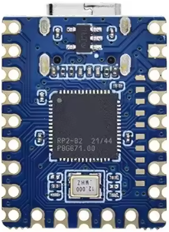
The RP2040-BackPins are the exposed pins located on the back of the RP2040 microcontroller. These pins provide easy access to the GPIO (General Purpose Input/Output), power, and communication interfaces, making them ideal for prototyping and circuit connections. By utilizing the RP2040-BackPins, developers can quickly interface with external components, sensors, and modules without the need for complex soldering or additional hardware.
Explore Projects Built with RP2040-BackPins
 Open Project in Cirkit Designer
 Open Project in Cirkit Designer
 Open Project in Cirkit Designer
 Open Project in Cirkit Designer
Explore Projects Built with RP2040-BackPins
Open Project in Cirkit DesignerOpen Project in Cirkit DesignerOpen Project in Cirkit DesignerOpen Project in Cirkit DesignerCommon Applications and Use Cases
- Prototyping circuits with breadboards or custom PCBs
- Connecting sensors, actuators, and other peripherals
- Accessing communication protocols such as I2C, SPI, and UART
- Powering external devices or modules
- Educational projects and rapid prototyping
Technical Specifications
Key Technical Details
- Microcontroller Compatibility: RP2040
- Voltage Levels: 3.3V logic (5V-tolerant on some pins)
- Maximum Current per GPIO Pin: 12 mA (source/sink)
- Total GPIO Pins: 30 (26 available for general use)
- Communication Interfaces: I2C, SPI, UART, PWM
- Power Pins: 3.3V, 5V, and GND available
- Pin Pitch: 2.54 mm (standard breadboard spacing)
Pin Configuration and Descriptions
The RP2040-BackPins are arranged in a standard 2.54 mm grid, making them compatible with breadboards and headers. Below is a table describing the pin configuration:
| Pin Number | Pin Name | Function | Description |
|---|---|---|---|
| 1 | GND | Ground | Common ground for the circuit |
| 2 | 3V3 | Power Output | 3.3V regulated output |
| 3 | 5V | Power Input/Output | 5V input or output (depending on power source) |
| 4 | GP0 | GPIO / UART0 TX | General-purpose I/O or UART0 transmit |
| 5 | GP1 | GPIO / UART0 RX | General-purpose I/O or UART0 receive |
| 6 | GP2 | GPIO / I2C1 SDA | General-purpose I/O or I2C1 data line |
| 7 | GP3 | GPIO / I2C1 SCL | General-purpose I/O or I2C1 clock line |
| 8 | GP4 | GPIO / PWM | General-purpose I/O or PWM output |
| 9 | GP5 | GPIO / PWM | General-purpose I/O or PWM output |
| ... | ... | ... | Additional GPIO pins follow a similar pattern |
| 30 | GP29 | GPIO / ADC3 | General-purpose I/O or ADC input (analog-to-digital converter) |
Note: Not all pins are 5V-tolerant. Refer to the RP2040 datasheet for detailed electrical characteristics.
Usage Instructions
How to Use the RP2040-BackPins in a Circuit
Powering the Circuit:
- Connect the
3V3pin to power components requiring 3.3V. - Use the
5Vpin to power components that require 5V (if the RP2040 is powered via USB). - Always connect the
GNDpin to the ground of your circuit.
- Connect the
Connecting Peripherals:
- Use GPIO pins (e.g.,
GP0,GP1, etc.) to interface with sensors, LEDs, or other devices. - For communication protocols, connect the appropriate pins:
- I2C:
GP2(SDA) andGP3(SCL) - SPI: Use designated SPI pins (refer to the RP2040 datasheet for details)
- UART:
GP0(TX) andGP1(RX)
- I2C:
- Use GPIO pins (e.g.,
Programming the RP2040:
- Use a micro-USB cable to upload code to the RP2040.
- Access the BackPins for prototyping while the microcontroller is powered and running.
Breadboard Compatibility:
- The 2.54 mm pin spacing allows direct insertion into standard breadboards or headers.
Important Considerations and Best Practices
- Voltage Levels: Ensure connected components are compatible with the 3.3V logic level of the RP2040.
- Current Limits: Do not exceed the maximum current rating of 12 mA per GPIO pin.
- Pin Protection: Avoid short circuits or overvoltage conditions to prevent damage to the microcontroller.
- Pull-Up/Pull-Down Resistors: Use external resistors if required for stable GPIO operation.
Example: Using RP2040-BackPins with Arduino IDE
The RP2040 can be programmed using the Arduino IDE. Below is an example of blinking an LED connected to GP2:
// Define the GPIO pin for the LED
#define LED_PIN 2

void setup() {
  pinMode(LED_PIN, OUTPUT); // Set GP2 as an output pin
}

void loop() {
  digitalWrite(LED_PIN, HIGH); // Turn the LED on
  delay(1000);                 // Wait for 1 second
  digitalWrite(LED_PIN, LOW);  // Turn the LED off
  delay(1000);                 // Wait for 1 second
}
Note: Ensure the Arduino IDE is configured for the RP2040 board before uploading the code.
Troubleshooting and FAQs
Common Issues and Solutions
No Power to External Components:
- Cause: Incorrect connection to power pins.
- Solution: Verify that the
3V3or5Vpin is properly connected to the component.
GPIO Pin Not Responding:
- Cause: Incorrect pin configuration in the code.
- Solution: Double-check the pin number and ensure it is set as input/output in the code.
Communication Protocol Not Working:
- Cause: Misconfigured I2C, SPI, or UART connections.
- Solution: Verify the wiring and ensure the correct pins are used for the protocol.
Overheating or Damage:
- Cause: Exceeding current or voltage limits.
- Solution: Ensure all connected components operate within the RP2040's electrical specifications.
FAQs
Q: Can I use 5V logic devices with the RP2040-BackPins?
A: Only some pins are 5V-tolerant. Check the RP2040 datasheet for specific pin tolerances. Use level shifters if needed.
Q: How do I identify the pin numbers on the BackPins?
A: Refer to the pinout diagram provided in the RP2040 documentation or silkscreen labels on the board.
Q: Can I power the RP2040 through the BackPins?
A: Yes, you can power the RP2040 by supplying 5V to the 5V pin or 3.3V to the 3V3 pin. Ensure proper grounding.
Q: What is the maximum current I can draw from the 3.3V pin?
A: The maximum current depends on the power source (e.g., USB). Typically, it is around 500 mA when powered via USB.
By following this documentation, you can effectively utilize the RP2040-BackPins for your projects and prototypes.