How to Use PLC: Examples, Pinouts, and Specs
Introduction
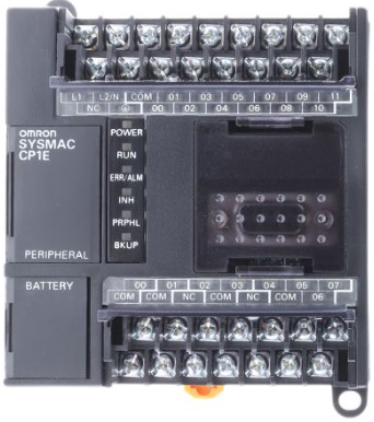
The OMRON CP1E is a Programmable Logic Controller (PLC) designed for control and automation of various electromechanical processes in industrial environments. This PLC is part of OMRON's CP1E series, known for its reliability, durability, and flexibility. It is commonly used in applications such as conveyor systems, sensor management, and process control where robust and precise control is required.
Explore Projects Built with PLC


Explore Projects Built with PLC
Technical Specifications
General Features
- Supply Voltage: 100-240 VAC or 24 VDC (depending on model)
- Input/Output Count: Varies by model (e.g., 10, 20, 30, 40 I/O points)
- Program Capacity: Up to 8k steps
- Data Memory: Up to 10k words
- High-Speed Counters: Up to 100 kHz
- Pulse Outputs: Up to 100 kHz for transistor output models
- Communication Ports: USB, Optional RS-232C/485
Pin Configuration and Descriptions
| Pin No. | Description | Notes |
|---|---|---|
| 1 | Input 0 | Digital input |
| 2 | Input 1 | Digital input |
| ... | ... | ... |
| n | Input n-1 | Digital input (n varies by model) |
| n+1 | Output 0 | Digital output |
| n+2 | Output 1 | Digital output |
| ... | ... | ... |
| m | Output m-n-1 | Digital output (m varies by model) |
| COM | Common Terminal | For sinking/sourcing outputs |
| L/N | AC Power Supply Input | For 100-240 VAC models |
| +V/-V | DC Power Supply Input | For 24 VDC models |
Note: The pin configuration above is a simplified representation. The actual PLC has multiple terminals for inputs, outputs, power supply, and communication ports. Refer to the specific model's datasheet for exact details.
Usage Instructions
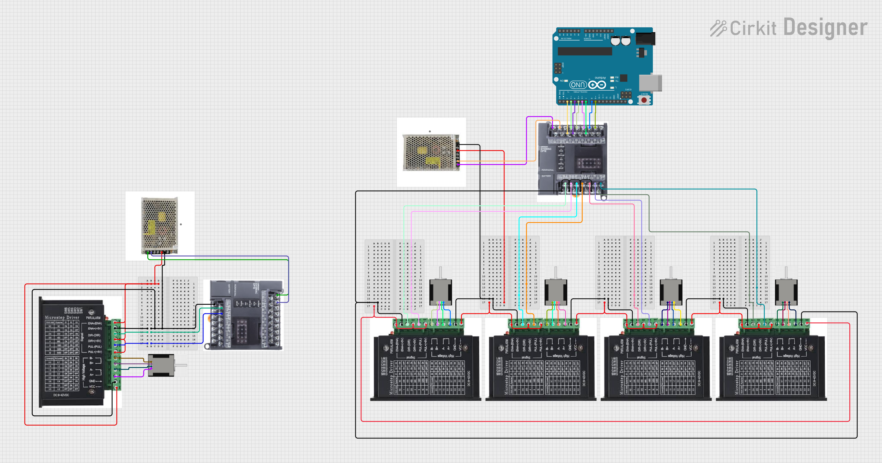
Wiring the PLC
- Power Supply: Connect the power supply to the PLC according to the model's voltage requirements (AC or DC).
- Inputs/Outputs: Wire the digital inputs and outputs to the corresponding terminals. Ensure proper isolation and protection for each I/O point.
- Communication: Connect the communication port to a PC or HMI for programming and monitoring.
Programming the PLC
- Software: Use OMRON's CX-Programmer or other compatible software for programming the CP1E PLC.
- Logic Development: Develop the control logic using ladder diagrams, function blocks, or structured text as per the application's requirements.
- Simulation: Test the logic using the software's simulation features before downloading it to the PLC.
Best Practices
- Always follow industrial safety standards when installing and operating the PLC.
- Use proper cable shielding and grounding to minimize electrical noise and interference.
- Regularly back up the PLC program and maintain documentation for future reference.
Troubleshooting and FAQs
Common Issues
- PLC Not Powering On: Check the power supply connections and voltage levels. Ensure that the PLC's power switch (if available) is turned on.
- Inputs/Outputs Not Responding: Verify the wiring and check for any blown fuses or tripped circuit breakers. Ensure that the I/O points are correctly configured in the program.
- Communication Errors: Check the communication cable and port settings. Ensure that the correct driver is installed on the PC.
FAQs
Q: Can the CP1E PLC be used for motion control applications? A: Yes, the CP1E series supports high-speed counters and pulse outputs suitable for basic motion control.
Q: How do I connect the CP1E PLC to a computer for programming? A: Use a USB cable to connect the PLC to a computer with the CX-Programmer software installed.
Q: What is the maximum operating temperature for the CP1E PLC? A: The operating temperature range is typically from 0°C to 55°C, but always refer to the specific model's datasheet for precise information.
For more detailed troubleshooting and additional FAQs, refer to the OMRON CP1E user manual and technical support resources.
Note: This documentation is a general guide and does not cover all possible configurations or models of the OMRON CP1E PLC. Always consult the specific datasheet and manuals for detailed information on your particular model.