How to Use ST3215 Servo: Examples, Pinouts, and Specs
Introduction
The ST3215 Servo, manufactured by Waveshare, is a high-torque, precision servo motor designed for robotics and automation applications. Its compact design makes it ideal for projects requiring accurate position control and smooth motion. With a wide range of motion and reliable performance, the ST3215 Servo is a versatile component for hobbyists and professionals alike.
Explore Projects Built with ST3215 Servo

Explore Projects Built with ST3215 Servo
Common Applications
- Robotic arms and manipulators
- RC vehicles and drones
- Automated systems and machinery
- Pan-tilt camera mounts
- Educational and DIY electronics projects
Technical Specifications
The following table outlines the key technical details of the ST3215 Servo:
| Parameter | Value |
|---|---|
| Operating Voltage | 4.8V to 6.0V |
| Stall Torque | 15 kg·cm @ 6.0V |
| Operating Speed | 0.12 sec/60° @ 6.0V |
| Control Signal | PWM (Pulse Width Modulation) |
| PWM Pulse Range | 500 µs to 2500 µs |
| Angle Range | 0° to 180° |
| Dimensions | 40.5 x 20 x 38 mm |
| Weight | 55 g |
| Connector Type | 3-pin female header |
Pin Configuration
The ST3215 Servo has a standard 3-pin connector. The pinout is as follows:
| Pin | Wire Color | Description |
|---|---|---|
| 1 | Brown | Ground (GND) |
| 2 | Red | Power (VCC) |
| 3 | Orange | Signal (PWM Input) |
Usage Instructions
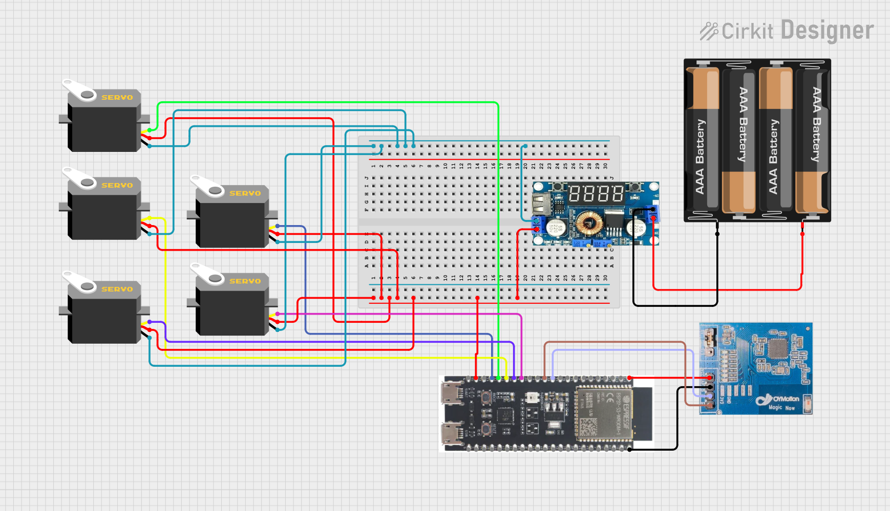
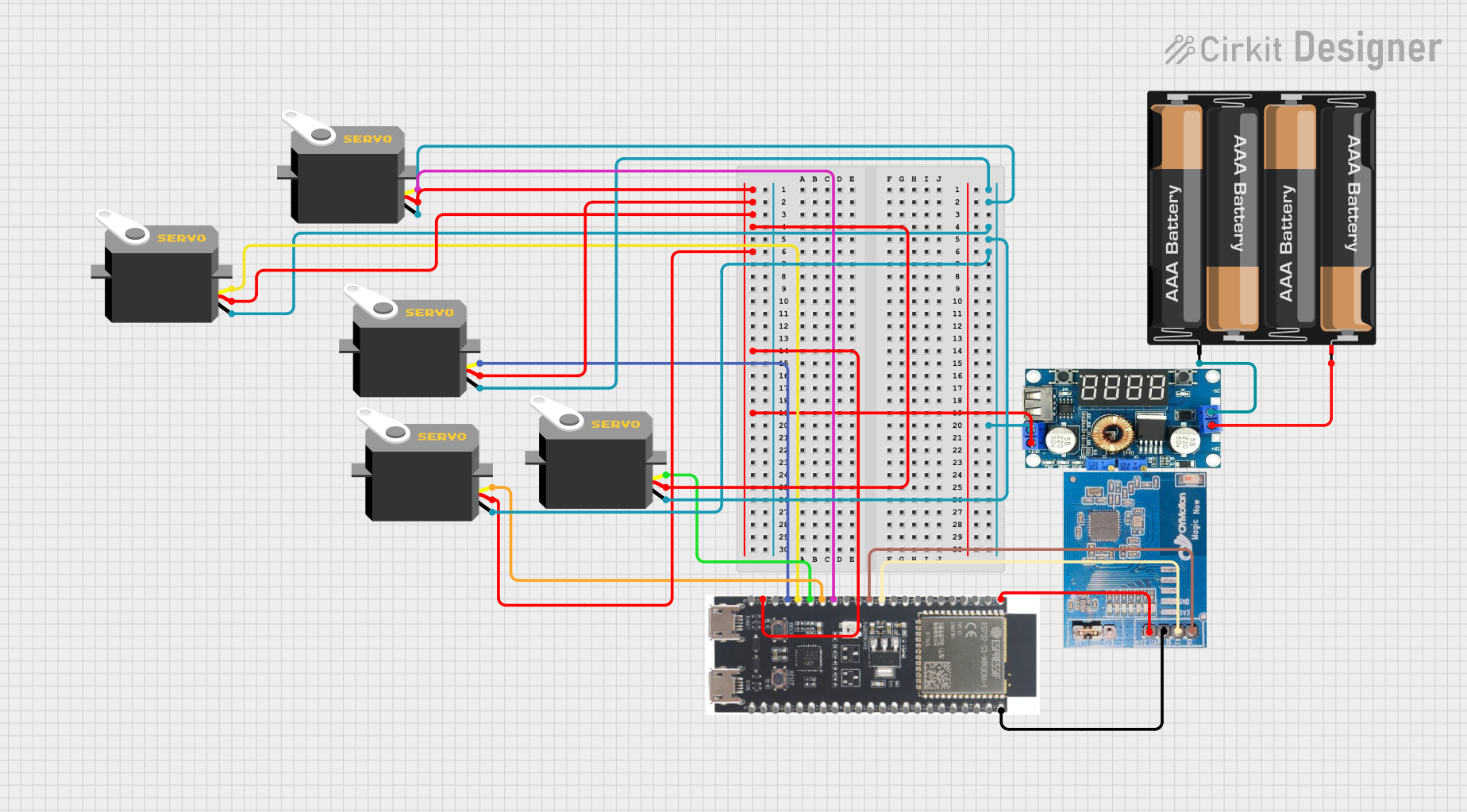
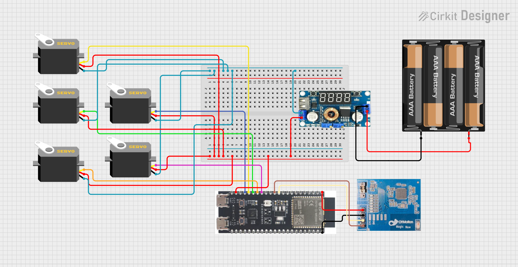
How to Use the ST3215 Servo in a Circuit
- Power Supply: Connect the red wire to a power source (4.8V to 6.0V). Ensure the power supply can provide sufficient current for the servo's operation.
- Ground Connection: Connect the brown wire to the ground (GND) of your circuit.
- Signal Input: Connect the orange wire to a PWM-capable pin on your microcontroller (e.g., Arduino UNO).
- PWM Signal: Generate a PWM signal with a pulse width between 500 µs (0°) and 2500 µs (180°) to control the servo's position.
Important Considerations
- Power Requirements: Use a dedicated power supply for the servo if your circuit includes multiple components, as servos can draw significant current.
- Signal Stability: Ensure the PWM signal is stable and within the specified range to avoid erratic behavior.
- Mechanical Limits: Do not force the servo beyond its physical range of motion (0° to 180°) to prevent damage.
Example Code for Arduino UNO
Below is an example of how to control the ST3215 Servo using an Arduino UNO:
#include <Servo.h> // Include the Servo library

Servo st3215; // Create a Servo object for the ST3215

void setup() {
  st3215.attach(9); // Attach the servo to pin 9 on the Arduino
}

void loop() {
  st3215.write(0); // Move the servo to 0 degrees
  delay(1000);     // Wait for 1 second

  st3215.write(90); // Move the servo to 90 degrees
  delay(1000);      // Wait for 1 second

  st3215.write(180); // Move the servo to 180 degrees
  delay(1000);       // Wait for 1 second
}
Best Practices
- Use a capacitor across the power and ground lines to reduce noise and voltage fluctuations.
- Avoid sudden changes in position to minimize wear on the servo gears.
- Test the servo with a low load before integrating it into your project.
Troubleshooting and FAQs
Common Issues and Solutions
Servo Not Moving
- Cause: Incorrect wiring or insufficient power supply.
- Solution: Double-check the connections and ensure the power supply meets the voltage and current requirements.
Erratic Movement
- Cause: Unstable PWM signal or electrical noise.
- Solution: Verify the PWM signal is within the specified range and add a capacitor to filter noise.
Overheating
- Cause: Prolonged operation under high load or insufficient ventilation.
- Solution: Reduce the load on the servo and ensure proper airflow around the component.
Limited Range of Motion
- Cause: Incorrect PWM pulse width or mechanical obstruction.
- Solution: Check the PWM signal and ensure there are no physical obstructions.
FAQs
Q: Can I power the ST3215 Servo directly from the Arduino UNO?
A: While it is possible, it is not recommended. The Arduino's 5V pin may not provide enough current for the servo, especially under load. Use an external power supply for optimal performance.
Q: What happens if I send a PWM signal outside the specified range?
A: The servo may behave unpredictably or attempt to move beyond its physical limits, potentially causing damage. Always keep the PWM signal within the 500 µs to 2500 µs range.
Q: Can I use the ST3215 Servo with a Raspberry Pi?
A: Yes, but you will need a PWM driver or library to generate a stable PWM signal, as the Raspberry Pi's GPIO pins do not natively support hardware PWM.
Q: How do I know if the servo is overloaded?
A: Signs of overloading include reduced speed, erratic movement, or overheating. Reduce the load or use a higher-torque servo if needed.