How to Use 128x64 0.96 inch SPI Monochrome OLED display: Examples, Pinouts, and Specs
Introduction
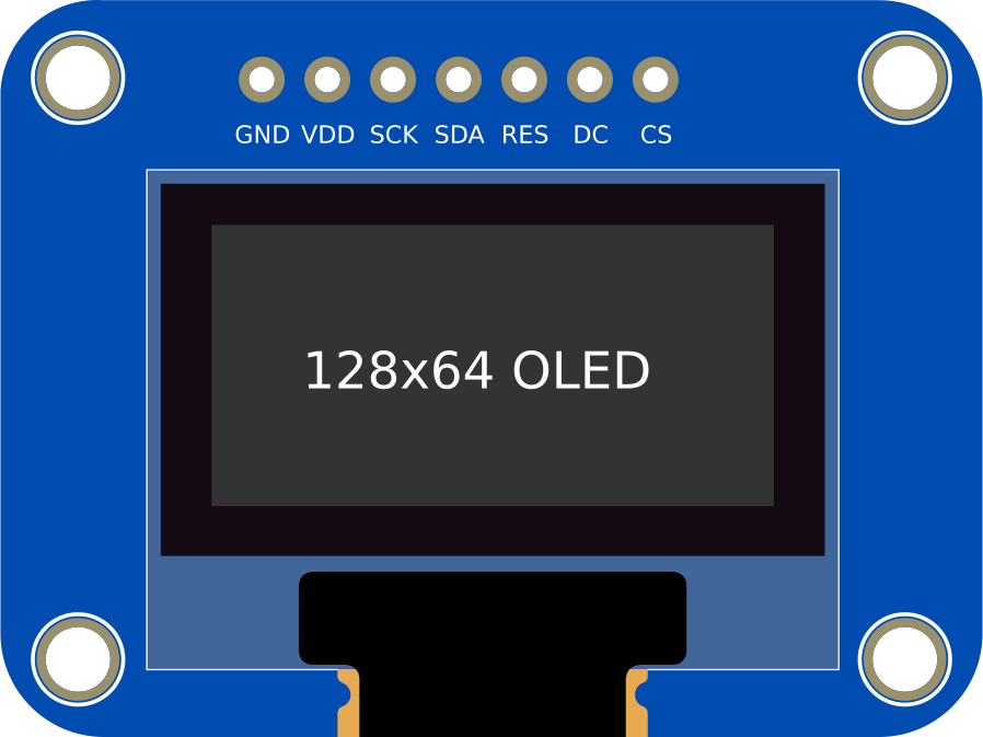
The 128x64 0.96 inch SPI Monochrome OLED display is a compact and versatile display module with a resolution of 128x64 pixels. It uses SPI (Serial Peripheral Interface) for communication, ensuring fast and efficient data transfer. This display is known for its high contrast, low power consumption, and wide viewing angles, making it an excellent choice for embedded systems, portable devices, and DIY electronics projects.
Explore Projects Built with 128x64 0.96 inch SPI Monochrome OLED display


Explore Projects Built with 128x64 0.96 inch SPI Monochrome OLED display
Common Applications and Use Cases
- Wearable devices and smartwatches
- IoT (Internet of Things) projects
- Portable measurement instruments
- Home automation systems
- Displaying text, graphics, or sensor data in microcontroller-based projects
Technical Specifications
Key Technical Details
| Parameter | Value |
|---|---|
| Display Type | Monochrome OLED |
| Resolution | 128x64 pixels |
| Communication Interface | SPI (Serial Peripheral Interface) |
| Operating Voltage | 3.3V - 5V |
| Power Consumption | ~0.04W (typical) |
| Display Size | 0.96 inch (diagonal) |
| Viewing Angle | >160° |
| Driver IC | SSD1306 |
| Operating Temperature | -40°C to +85°C |
Pin Configuration and Descriptions
| Pin Name | Pin Number | Description |
|---|---|---|
| GND | 1 | Ground pin. Connect to the ground of the power supply. |
| VCC | 2 | Power supply pin. Connect to 3.3V or 5V. |
| D0 (SCK) | 3 | SPI clock pin. Connect to the SCK pin of the microcontroller. |
| D1 (MOSI) | 4 | SPI data pin. Connect to the MOSI pin of the microcontroller. |
| RES | 5 | Reset pin. Used to reset the display. |
| DC | 6 | Data/Command pin. Determines whether data or commands are sent. |
| CS | 7 | Chip Select pin. Enables communication with the display. |
Usage Instructions
How to Use the Component in a Circuit
- Power Connection: Connect the
VCCpin to a 3.3V or 5V power source and theGNDpin to the ground. - SPI Communication: Connect the
D0 (SCK)andD1 (MOSI)pins to the corresponding SPI pins on your microcontroller. - Control Pins:
- Connect the
RESpin to a GPIO pin on the microcontroller for resetting the display. - Connect the
DCpin to a GPIO pin to toggle between data and command modes. - Connect the
CSpin to a GPIO pin to enable or disable communication with the display.
- Connect the
- Install Libraries: If using an Arduino, install the
Adafruit SSD1306andAdafruit GFXlibraries for easy control of the display.
Important Considerations and Best Practices
- Ensure the power supply voltage matches the display's operating voltage (3.3V or 5V).
- Use appropriate pull-up resistors for SPI lines if required by your microcontroller.
- Avoid touching the display surface to prevent damage or smudges.
- Use a level shifter if your microcontroller operates at 5V logic and the display at 3.3V.
Example Code for Arduino UNO
#include <Adafruit_GFX.h>      // Graphics library for OLED
#include <Adafruit_SSD1306.h> // Library for SSD1306 OLED driver

#define SCREEN_WIDTH 128       // OLED display width, in pixels
#define SCREEN_HEIGHT 64       // OLED display height, in pixels

// Declaration for SPI OLED display
#define OLED_RESET     4       // Reset pin (can be any GPIO pin)
#define OLED_DC        5       // Data/Command pin
#define OLED_CS        10      // Chip Select pin
Adafruit_SSD1306 display(SCREEN_WIDTH, SCREEN_HEIGHT, &SPI, OLED_DC, OLED_RESET, OLED_CS);

void setup() {
  // Initialize serial communication for debugging
  Serial.begin(9600);

  // Initialize the OLED display
  if (!display.begin(SSD1306_SWITCHCAPVCC, 0x3C)) { // Address 0x3C for 128x64
    Serial.println(F("SSD1306 allocation failed"));
    for (;;); // Loop forever if initialization fails
  }

  display.clearDisplay(); // Clear the buffer
  display.setTextSize(1); // Set text size to 1
  display.setTextColor(SSD1306_WHITE); // Set text color to white
  display.setCursor(0, 0); // Set cursor to top-left corner
  display.println(F("Hello, OLED!")); // Print text to the buffer
  display.display(); // Display the buffer on the screen
}

void loop() {
  // Nothing to do here
}
Troubleshooting and FAQs
Common Issues and Solutions
Display Not Turning On:
- Ensure the
VCCandGNDpins are properly connected. - Verify that the power supply voltage matches the display's requirements.
- Ensure the
No Output on the Display:
- Check the SPI connections (
D0,D1,CS,DC,RES) for proper wiring. - Ensure the correct I2C address (
0x3Cor0x3D) is used in the code.
- Check the SPI connections (
Flickering or Unstable Display:
- Verify that the SPI clock speed is within the display's supported range.
- Use shorter wires to reduce noise in the SPI communication.
Library Errors During Compilation:
- Ensure the
Adafruit SSD1306andAdafruit GFXlibraries are installed and up to date. - Restart the Arduino IDE after installing the libraries.
- Ensure the
FAQs
Q: Can this display be used with 3.3V microcontrollers like ESP32?
A: Yes, the display is compatible with both 3.3V and 5V logic levels, making it suitable for microcontrollers like ESP32, Arduino, and others.
Q: How do I display custom graphics?
A: You can use the Adafruit GFX library to draw shapes, bitmaps, and custom graphics. Refer to the library documentation for detailed instructions.
Q: Can I use this display with I2C instead of SPI?
A: This specific model is designed for SPI communication. However, there are similar OLED displays available that support I2C.
Q: What is the maximum SPI clock speed supported?
A: The SSD1306 driver typically supports SPI clock speeds up to 10 MHz. Check your microcontroller's capabilities for compatibility.