Cirkit Designer Logo
Cirkit Designer
Your all-in-one circuit design IDE
Home / 
Component Documentation

How to Use DS-K2602T: Examples, Pinouts, and Specs

Image of DS-K2602T
Cirkit Designer LogoDesign with DS-K2602T in Cirkit Designer

Introduction

The DS-K2602T is a biometric access control terminal designed for secure and efficient entry management. It utilizes advanced fingerprint recognition technology to ensure high levels of security. This device supports multiple authentication methods, including fingerprint, card, and PIN, making it versatile for various applications. Its user-friendly interface and robust integration capabilities allow seamless operation with existing security systems.

Explore Projects Built with DS-K2602T

Use Cirkit Designer to design, explore, and prototype these projects online. Some projects support real-time simulation. Click "Open Project" to start designing instantly!
Arduino Mega 2560 Based Security System with Fingerprint Authentication and SMS Alerts
Image of Door security system: A project utilizing DS-K2602T in a practical application
This circuit features an Arduino Mega 2560 microcontroller interfaced with a SIM800L GSM module, two fingerprint scanners, an I2C LCD display, an IR sensor, and a piezo buzzer. Power management is handled by a PowerBoost 1000 Basic Pad USB, a TP4056 charging module, and a Li-ion 18650 battery, with an option to use a Mini AC-DC 110V-230V to 5V 700mA module for direct power supply. The primary functionality appears to be a security system with GSM communication capabilities, biometric access control, and visual/audible feedback.
Cirkit Designer LogoOpen Project in Cirkit Designer
Stepper Motor Control System with TB6600 Driver and DKC-1A Controller
Image of Copy of Copy of PLC-Based Step Motor Speed and Direction Control System: A project utilizing DS-K2602T in a practical application
This circuit controls a bipolar stepper motor using a tb6600 micro stepping motor driver and a DKC-1A stepper motor controller. The system is powered by a 24VDC power supply and includes a relay module for additional control functionalities.
Cirkit Designer LogoOpen Project in Cirkit Designer
Cellular-Enabled IoT Device with Real-Time Clock and Power Management
Image of LRCM PHASE 2 BASIC: A project utilizing DS-K2602T in a practical application
This circuit features a LilyGo-SIM7000G module for cellular communication and GPS functionality, interfaced with an RTC DS3231 for real-time clock capabilities. It includes voltage sensing through two voltage sensor modules, and uses an 8-channel opto-coupler for isolating different parts of the circuit. Power management is handled by a buck converter connected to a DC power source and batteries, with a fuse for protection and a rocker switch for on/off control. Additionally, there's an LED for indication purposes.
Cirkit Designer LogoOpen Project in Cirkit Designer
ESP32-Powered Wi-Fi Controlled Robotic Car with OLED Display and Ultrasonic Sensor
Image of playbot: A project utilizing DS-K2602T in a practical application
This circuit is a battery-powered system featuring an ESP32 microcontroller that controls an OLED display, a motor driver for two hobby motors, an ultrasonic sensor for distance measurement, and a DFPlayer Mini for audio output through a loudspeaker. The TP4056 module manages battery charging, and a step-up boost converter provides a stable 5V supply to the components.
Cirkit Designer LogoOpen Project in Cirkit Designer

Explore Projects Built with DS-K2602T

Use Cirkit Designer to design, explore, and prototype these projects online. Some projects support real-time simulation. Click "Open Project" to start designing instantly!
Image of Door security system: A project utilizing DS-K2602T in a practical application
Arduino Mega 2560 Based Security System with Fingerprint Authentication and SMS Alerts
This circuit features an Arduino Mega 2560 microcontroller interfaced with a SIM800L GSM module, two fingerprint scanners, an I2C LCD display, an IR sensor, and a piezo buzzer. Power management is handled by a PowerBoost 1000 Basic Pad USB, a TP4056 charging module, and a Li-ion 18650 battery, with an option to use a Mini AC-DC 110V-230V to 5V 700mA module for direct power supply. The primary functionality appears to be a security system with GSM communication capabilities, biometric access control, and visual/audible feedback.
Cirkit Designer LogoOpen Project in Cirkit Designer
Image of Copy of Copy of PLC-Based Step Motor Speed and Direction Control System: A project utilizing DS-K2602T in a practical application
Stepper Motor Control System with TB6600 Driver and DKC-1A Controller
This circuit controls a bipolar stepper motor using a tb6600 micro stepping motor driver and a DKC-1A stepper motor controller. The system is powered by a 24VDC power supply and includes a relay module for additional control functionalities.
Cirkit Designer LogoOpen Project in Cirkit Designer
Image of LRCM PHASE 2 BASIC: A project utilizing DS-K2602T in a practical application
Cellular-Enabled IoT Device with Real-Time Clock and Power Management
This circuit features a LilyGo-SIM7000G module for cellular communication and GPS functionality, interfaced with an RTC DS3231 for real-time clock capabilities. It includes voltage sensing through two voltage sensor modules, and uses an 8-channel opto-coupler for isolating different parts of the circuit. Power management is handled by a buck converter connected to a DC power source and batteries, with a fuse for protection and a rocker switch for on/off control. Additionally, there's an LED for indication purposes.
Cirkit Designer LogoOpen Project in Cirkit Designer
Image of playbot: A project utilizing DS-K2602T in a practical application
ESP32-Powered Wi-Fi Controlled Robotic Car with OLED Display and Ultrasonic Sensor
This circuit is a battery-powered system featuring an ESP32 microcontroller that controls an OLED display, a motor driver for two hobby motors, an ultrasonic sensor for distance measurement, and a DFPlayer Mini for audio output through a loudspeaker. The TP4056 module manages battery charging, and a step-up boost converter provides a stable 5V supply to the components.
Cirkit Designer LogoOpen Project in Cirkit Designer

Common Applications and Use Cases

  • Office buildings and corporate environments for employee access control
  • Residential complexes for secure entry management
  • Educational institutions to monitor and control access to restricted areas
  • Industrial facilities requiring multi-layered security
  • Integration with larger security systems for comprehensive access management

Technical Specifications

Key Technical Details

Parameter Specification
Power Supply 12 V DC ± 10%
Power Consumption ≤ 10 W
Fingerprint Capacity 3,000 templates
Card Capacity 100,000 cards
Log Capacity 300,000 events
Communication Interface TCP/IP, RS-485
Authentication Methods Fingerprint, Card, PIN, or combinations
Operating Temperature -10°C to 55°C (14°F to 131°F)
Operating Humidity 10% to 90% (non-condensing)
Dimensions 200 mm × 90 mm × 35 mm

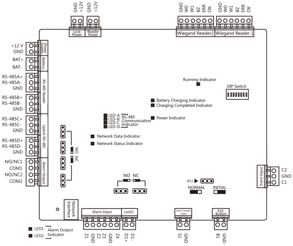
Pin Configuration and Descriptions

The DS-K2602T features a terminal block for wiring connections. Below is the pin configuration:

Pin Number Label Description
1 GND Ground connection
2 12V Power supply input (12 V DC)
3 RS485+ RS-485 communication line (positive)
4 RS485- RS-485 communication line (negative)
5 Wiegand D0 Wiegand data line 0
6 Wiegand D1 Wiegand data line 1
7 IN1 Input signal 1 (e.g., door sensor)
8 OUT1 Output signal 1 (e.g., door lock)

Usage Instructions

How to Use the DS-K2602T in a Circuit

  1. Power Connection: Connect the 12V pin to a 12 V DC power supply and the GND pin to ground.
  2. Communication Setup: Use the RS485+ and RS485- pins for RS-485 communication or connect the device to a network via TCP/IP.
  3. Peripheral Integration:
    • Connect door sensors to the IN1 pin.
    • Connect door locks or alarms to the OUT1 pin.
  4. Authentication Configuration:
    • Enroll fingerprints, cards, or PINs using the device's interface or management software.
    • Configure authentication modes (e.g., fingerprint-only, card + PIN) as required.

Important Considerations and Best Practices

  • Ensure the power supply is stable and within the specified range (12 V DC ± 10%).
  • Avoid exposing the device to extreme temperatures or humidity beyond the operating range.
  • Regularly clean the fingerprint sensor to maintain accuracy.
  • Use shielded cables for RS-485 communication to minimize interference.
  • For enhanced security, enable multi-factor authentication (e.g., fingerprint + PIN).

Arduino UNO Integration Example

The DS-K2602T can communicate with an Arduino UNO via RS-485. Below is an example code snippet for interfacing:

#include <SoftwareSerial.h>

// Define RS-485 communication pins
#define RS485_RX 10  // Arduino pin connected to RS-485 receiver
#define RS485_TX 11  // Arduino pin connected to RS-485 transmitter

SoftwareSerial rs485(RS485_RX, RS485_TX); // Initialize software serial

void setup() {
  Serial.begin(9600); // Start serial communication with PC
  rs485.begin(9600);  // Start RS-485 communication

  Serial.println("DS-K2602T RS-485 Communication Initialized");
}

void loop() {
  // Check if data is available from the DS-K2602T
  if (rs485.available()) {
    String data = "";
    while (rs485.available()) {
      char c = rs485.read(); // Read a byte from RS-485
      data += c;
    }
    Serial.println("Received from DS-K2602T: " + data);
  }

  // Example: Send a command to the DS-K2602T
  if (Serial.available()) {
    String command = Serial.readString();
    rs485.print(command); // Send command via RS-485
    Serial.println("Command sent to DS-K2602T: " + command);
  }
}

Note: Use an RS-485 module to interface the Arduino UNO with the DS-K2602T. Ensure proper wiring between the module and the Arduino.

Troubleshooting and FAQs

Common Issues and Solutions

  1. Device Not Powering On:

    • Verify the power supply voltage is within the specified range (12 V DC ± 10%).
    • Check the wiring connections for loose or incorrect connections.
  2. Fingerprint Recognition Fails:

    • Ensure the fingerprint sensor is clean and free of debris.
    • Re-enroll the fingerprint if recognition issues persist.
  3. Communication Failure:

    • Confirm the RS-485 or TCP/IP connections are secure.
    • Check the baud rate and communication settings in the management software.
  4. Door Lock Not Activating:

    • Verify the wiring between the OUT1 pin and the door lock.
    • Ensure the door lock is functioning correctly and receiving power.

FAQs

Q1: Can the DS-K2602T be used outdoors?
A1: The DS-K2602T is not weatherproof. Use it indoors or in a protected environment.

Q2: How many users can the device support?
A2: The device supports up to 3,000 fingerprint templates and 100,000 card users.

Q3: Can I integrate the DS-K2602T with third-party security systems?
A3: Yes, the device supports Wiegand and RS-485 protocols for integration with third-party systems.

Q4: What happens if the power supply is interrupted?
A4: The DS-K2602T retains user data and logs in non-volatile memory, ensuring no data loss during power outages.