Cirkit Designer
Your all-in-one circuit design IDE
Home /
Component Documentation
How to Use Flood Sensor: Examples, Pinouts, and Specs
Introduction
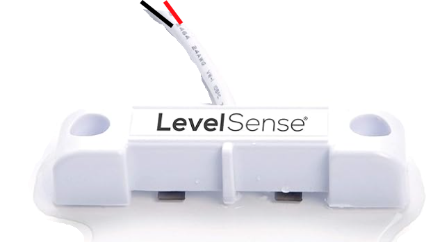
The Flood Sensor is a device designed to detect the presence of water and alert users to potential flooding. This sensor is commonly used in basements, bathrooms, kitchens, and other areas prone to water damage. By providing early warnings, it helps prevent extensive damage and costly repairs.
Explore Projects Built with Flood Sensor
Arduino UNO Flood Management System with Ultrasonic Sensor and Wi-Fi Connectivity
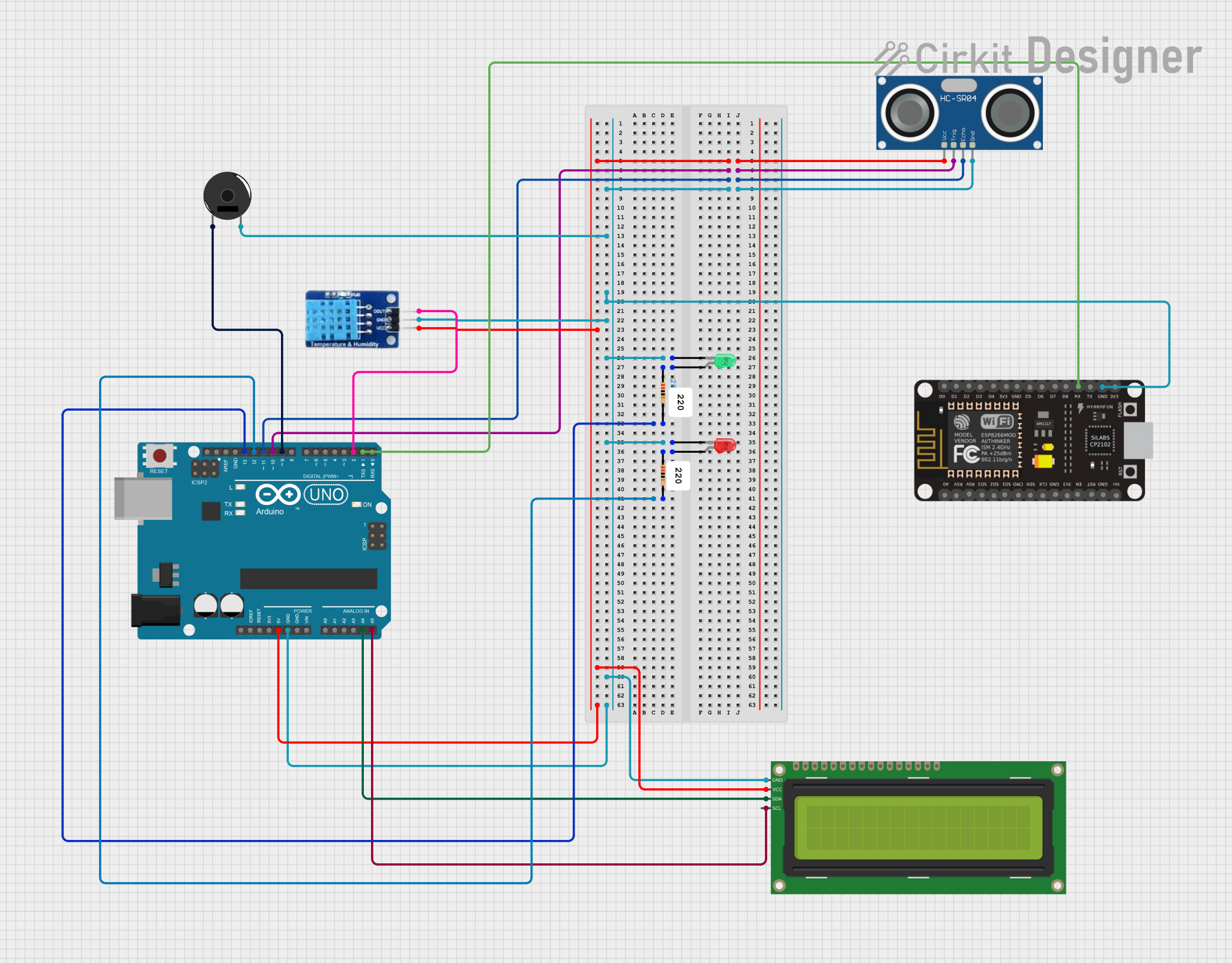
This circuit is a flood management system that uses an Arduino UNO to monitor water levels, temperature, and humidity. It employs an HC-SR04 ultrasonic sensor for distance measurement, a DHT11 sensor for temperature and humidity, and displays the data on a 16x2 I2C LCD. Additionally, it includes a piezo buzzer and LEDs to provide alerts when water levels exceed a safety threshold.
NodeMCU ESP8266 Flood Monitoring System with GSM Alert and Ultrasonic Sensor

This circuit is designed for a flood monitoring system. It uses a NodeMCU ESP8266 to read data from an HC-SR04 ultrasonic sensor and a float switch to detect water levels, and displays this information on an I2C LCD screen. Additionally, the circuit can send SMS alerts via a SIM800L GSM module when the water level exceeds a predefined threshold, indicating potential flooding.
Arduino-Based Automatic Drainage Water Monitoring & Flood Control System with Air Quality and Pressure Sensors
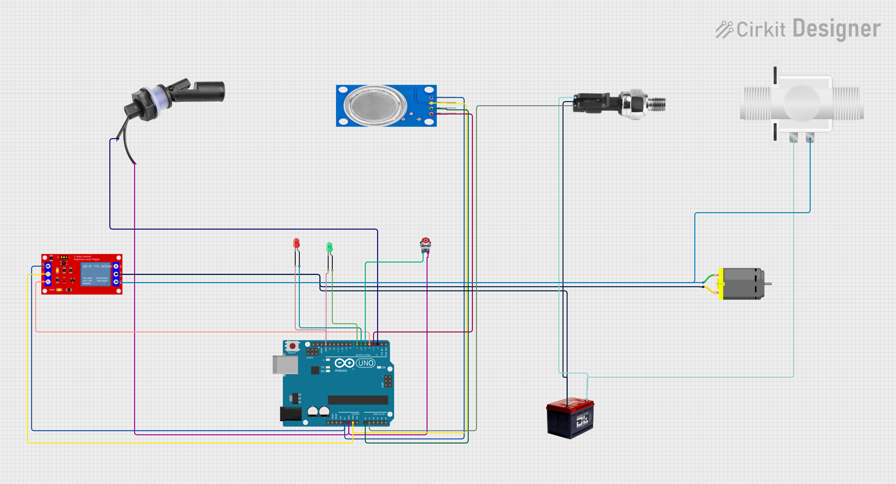
This circuit is an Arduino-based automatic drainage water monitoring and flood control system. It uses a float switch, MQ135 air quality sensor, and pressure sensor to monitor environmental conditions and control a relay module that operates a DC motor and solenoid valve. The system includes LEDs for status indication and a stop button to manually halt operations.
Arduino UNO Based Flood Alert System with GSM Notification and LCD Display
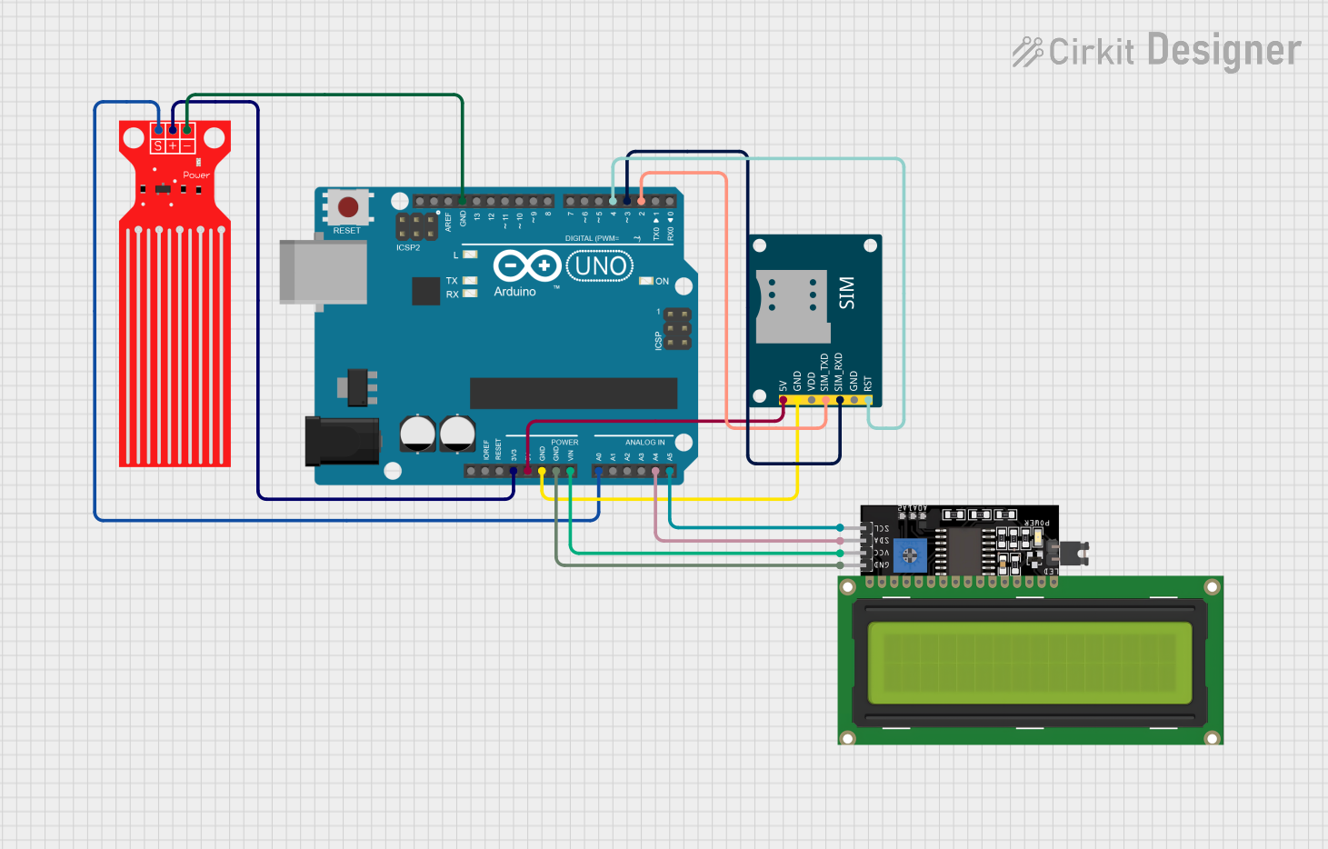
This circuit is designed as a flood alert system. It uses an Arduino UNO to monitor water levels through a Water Level Sensor and displays the readings on an LCD Display. When a certain threshold is exceeded, the Arduino uses a SIM800L GSM Module to send SMS alerts and make calls to a predefined phone number.
Explore Projects Built with Flood Sensor
Arduino UNO Flood Management System with Ultrasonic Sensor and Wi-Fi Connectivity
This circuit is a flood management system that uses an Arduino UNO to monitor water levels, temperature, and humidity. It employs an HC-SR04 ultrasonic sensor for distance measurement, a DHT11 sensor for temperature and humidity, and displays the data on a 16x2 I2C LCD. Additionally, it includes a piezo buzzer and LEDs to provide alerts when water levels exceed a safety threshold.
NodeMCU ESP8266 Flood Monitoring System with GSM Alert and Ultrasonic Sensor
This circuit is designed for a flood monitoring system. It uses a NodeMCU ESP8266 to read data from an HC-SR04 ultrasonic sensor and a float switch to detect water levels, and displays this information on an I2C LCD screen. Additionally, the circuit can send SMS alerts via a SIM800L GSM module when the water level exceeds a predefined threshold, indicating potential flooding.
Arduino-Based Automatic Drainage Water Monitoring & Flood Control System with Air Quality and Pressure Sensors
This circuit is an Arduino-based automatic drainage water monitoring and flood control system. It uses a float switch, MQ135 air quality sensor, and pressure sensor to monitor environmental conditions and control a relay module that operates a DC motor and solenoid valve. The system includes LEDs for status indication and a stop button to manually halt operations.
Arduino UNO Based Flood Alert System with GSM Notification and LCD Display
This circuit is designed as a flood alert system. It uses an Arduino UNO to monitor water levels through a Water Level Sensor and displays the readings on an LCD Display. When a certain threshold is exceeded, the Arduino uses a SIM800L GSM Module to send SMS alerts and make calls to a predefined phone number.
Technical Specifications
Key Technical Details
| Parameter | Value |
|---|---|
| Operating Voltage | 3.3V - 5V |
| Operating Current | < 20mA |
| Detection Area | 38mm x 38mm |
| Output Type | Digital (High/Low) |
| Response Time | < 500ms |
| Operating Temperature | -10°C to 50°C |
Pin Configuration and Descriptions
| Pin Number | Pin Name | Description |
|---|---|---|
| 1 | VCC | Power supply (3.3V - 5V) |
| 2 | GND | Ground |
| 3 | DO | Digital Output (High when water detected, Low otherwise) |
Usage Instructions
How to Use the Component in a Circuit
Power the Sensor:
- Connect the VCC pin to a 3.3V or 5V power supply.
- Connect the GND pin to the ground of the power supply.
Connect the Output:
- Connect the DO pin to a digital input pin on your microcontroller (e.g., Arduino UNO).
Example Circuit:
- VCC to 5V on Arduino UNO.
- GND to GND on Arduino UNO.
- DO to digital pin 2 on Arduino UNO.
Important Considerations and Best Practices
- Placement: Ensure the sensor is placed in an area where water is likely to accumulate. Avoid placing it in areas with high humidity or condensation, as this may cause false positives.
- Power Supply: Use a stable power supply to avoid erratic behavior.
- Testing: Regularly test the sensor to ensure it is functioning correctly.
Arduino UNO Example Code
// Define the pin connected to the DO pin of the flood sensor
const int floodSensorPin = 2;

// Define the pin connected to the onboard LED
const int ledPin = 13;

void setup() {
  // Initialize the serial communication
  Serial.begin(9600);

  // Set the flood sensor pin as input
  pinMode(floodSensorPin, INPUT);

  // Set the LED pin as output
  pinMode(ledPin, OUTPUT);
}

void loop() {
  // Read the state of the flood sensor
  int sensorState = digitalRead(floodSensorPin);

  // If water is detected
  if (sensorState == HIGH) {
    // Turn on the LED
    digitalWrite(ledPin, HIGH);

    // Print a message to the serial monitor
    Serial.println("Water detected!");
  } else {
    // Turn off the LED
    digitalWrite(ledPin, LOW);

    // Print a message to the serial monitor
    Serial.println("No water detected.");
  }

  // Wait for 500 milliseconds before the next loop
  delay(500);
}
Troubleshooting and FAQs
Common Issues Users Might Face
False Positives:
- Cause: High humidity or condensation.
- Solution: Ensure the sensor is placed in a dry area and only exposed to water when flooding occurs.
No Detection:
- Cause: Incorrect wiring or power supply issues.
- Solution: Double-check the wiring and ensure the power supply is stable and within the specified range.
Erratic Behavior:
- Cause: Unstable power supply or interference.
- Solution: Use a decoupling capacitor across the power supply pins to filter out noise.
Solutions and Tips for Troubleshooting
- Check Connections: Ensure all connections are secure and correct.
- Test with Multimeter: Use a multimeter to check the voltage levels at the sensor pins.
- Use Serial Monitor: Utilize the serial monitor in Arduino IDE to debug and monitor sensor readings.
By following this documentation, users can effectively integrate and utilize the Flood Sensor in their projects, ensuring timely alerts and preventing potential water damage.