Cirkit Designer Logo
Cirkit Designer
Your all-in-one circuit design IDE
Home / 
Component Documentation

How to Use Sabertooth 32A Dual Motor Driver: Examples, Pinouts, and Specs

Image of Sabertooth 32A Dual Motor Driver
Cirkit Designer LogoDesign with Sabertooth 32A Dual Motor Driver in Cirkit Designer

Introduction

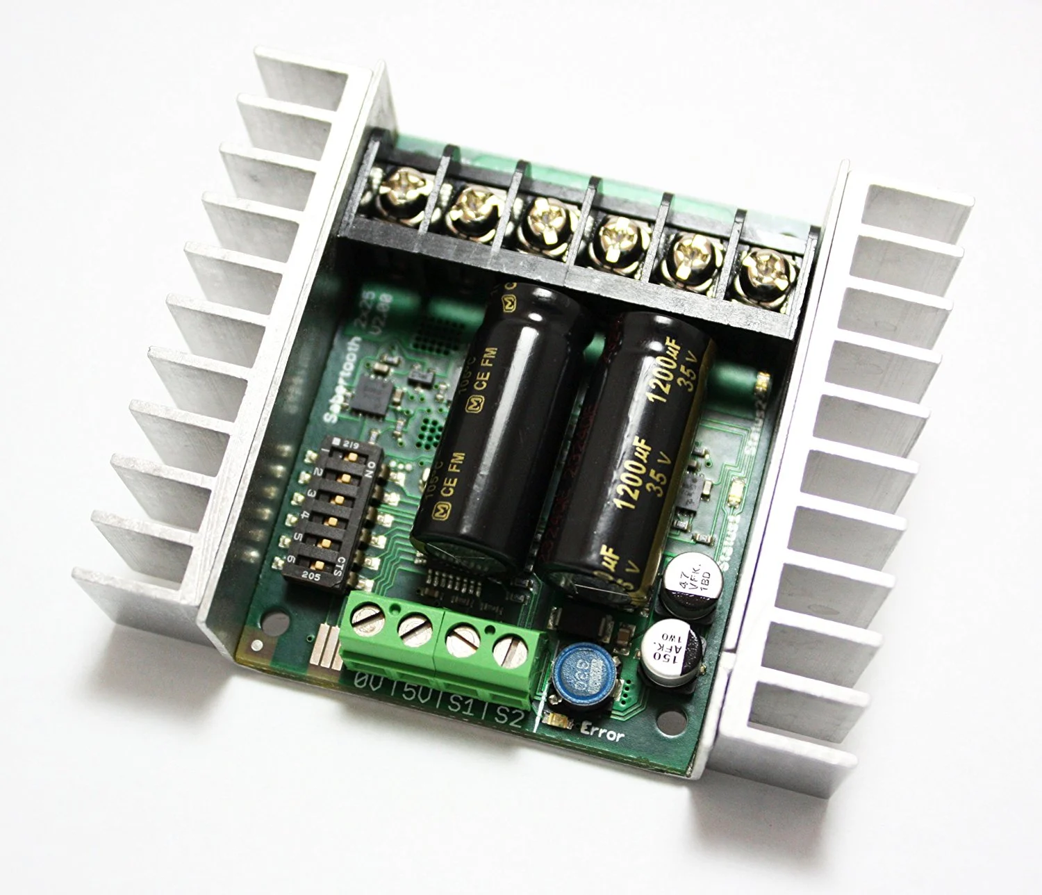
The Sabertooth 32A Dual Motor Driver is a robust and versatile motor driver designed to control two motors with a continuous current of 32A per channel. This component is widely used in robotics and automation applications where precise motor control is essential. Its high current capacity and ease of integration make it a popular choice for hobbyists and professionals alike.

Explore Projects Built with Sabertooth 32A Dual Motor Driver

Use Cirkit Designer to design, explore, and prototype these projects online. Some projects support real-time simulation. Click "Open Project" to start designing instantly!
ESP32-Controlled Dual Motor Driver with Optical Encoder Feedback
Image of Mobile Robot System with Speed and Position Control Using ESP32: A project utilizing Sabertooth 32A Dual Motor Driver in a practical application
This circuit is designed to control two DC motors using an L298N Dual Motor Driver Module, which receives PWM control signals from an ESP32 microcontroller. The motors' rotational movement can be monitored by two Optical Encoder Sensor Modules, which are also interfaced with the ESP32. Power is supplied by a 4 x AAA battery mount, with the 12V line powering the motor driver and the 5V line stepping down to power the ESP32 and the encoder sensors.
Cirkit Designer LogoOpen Project in Cirkit Designer
ESP32 and nRF24L01 Wi-Fi Controlled Dual Motor System
Image of SMARS with RF2401- DRV8833: A project utilizing Sabertooth 32A Dual Motor Driver in a practical application
This circuit is a remote-controlled dual-motor driver system using an ESP32 microcontroller. The ESP32 interfaces with an nRF24L01 wireless module for communication and a DRV8833 motor driver to control two motors, powered by a 2x 18650 battery pack regulated by an AMS1117 voltage regulator.
Cirkit Designer LogoOpen Project in Cirkit Designer
ESP32-Controlled Dual Motor Driver with Optical Encoder Feedback
Image of Copy of Mobile Robot System with Speed and Position Control Using ESP32: A project utilizing Sabertooth 32A Dual Motor Driver in a practical application
This circuit is designed to control two DC motors using an L298N Dual Motor Driver Module, which receives PWM control signals from an ESP32 microcontroller. The motors' rotational movement can be monitored by two Optical Encoder Sensor Modules connected to the ESP32. Power is supplied by a 4 x AAA battery mount, with the battery's positive terminal connected to the motor driver's 12V input and the negative terminal to the common ground.
Cirkit Designer LogoOpen Project in Cirkit Designer
ESP32 and TB6600/TB660 Stepper Motor Driver Joystick-Controlled Dual Stepper Motor System
Image of esp32_dual steppermotor: A project utilizing Sabertooth 32A Dual Motor Driver in a practical application
This circuit controls two NEMA23 stepper motors using TB6600 and TB660 stepper motor drivers, interfaced with an ESP32 microcontroller. The ESP32 reads inputs from a KY-023 Dual Axis Joystick Module to control the direction and movement of the motors, with power supplied by a 12V power source and regulated by a Step Up Boost Power Converter.
Cirkit Designer LogoOpen Project in Cirkit Designer

Explore Projects Built with Sabertooth 32A Dual Motor Driver

Use Cirkit Designer to design, explore, and prototype these projects online. Some projects support real-time simulation. Click "Open Project" to start designing instantly!
Image of Mobile Robot System with Speed and Position Control Using ESP32: A project utilizing Sabertooth 32A Dual Motor Driver in a practical application
ESP32-Controlled Dual Motor Driver with Optical Encoder Feedback
This circuit is designed to control two DC motors using an L298N Dual Motor Driver Module, which receives PWM control signals from an ESP32 microcontroller. The motors' rotational movement can be monitored by two Optical Encoder Sensor Modules, which are also interfaced with the ESP32. Power is supplied by a 4 x AAA battery mount, with the 12V line powering the motor driver and the 5V line stepping down to power the ESP32 and the encoder sensors.
Cirkit Designer LogoOpen Project in Cirkit Designer
Image of SMARS with RF2401- DRV8833: A project utilizing Sabertooth 32A Dual Motor Driver in a practical application
ESP32 and nRF24L01 Wi-Fi Controlled Dual Motor System
This circuit is a remote-controlled dual-motor driver system using an ESP32 microcontroller. The ESP32 interfaces with an nRF24L01 wireless module for communication and a DRV8833 motor driver to control two motors, powered by a 2x 18650 battery pack regulated by an AMS1117 voltage regulator.
Cirkit Designer LogoOpen Project in Cirkit Designer
Image of Copy of Mobile Robot System with Speed and Position Control Using ESP32: A project utilizing Sabertooth 32A Dual Motor Driver in a practical application
ESP32-Controlled Dual Motor Driver with Optical Encoder Feedback
This circuit is designed to control two DC motors using an L298N Dual Motor Driver Module, which receives PWM control signals from an ESP32 microcontroller. The motors' rotational movement can be monitored by two Optical Encoder Sensor Modules connected to the ESP32. Power is supplied by a 4 x AAA battery mount, with the battery's positive terminal connected to the motor driver's 12V input and the negative terminal to the common ground.
Cirkit Designer LogoOpen Project in Cirkit Designer
Image of esp32_dual steppermotor: A project utilizing Sabertooth 32A Dual Motor Driver in a practical application
ESP32 and TB6600/TB660 Stepper Motor Driver Joystick-Controlled Dual Stepper Motor System
This circuit controls two NEMA23 stepper motors using TB6600 and TB660 stepper motor drivers, interfaced with an ESP32 microcontroller. The ESP32 reads inputs from a KY-023 Dual Axis Joystick Module to control the direction and movement of the motors, with power supplied by a 12V power source and regulated by a Step Up Boost Power Converter.
Cirkit Designer LogoOpen Project in Cirkit Designer

Technical Specifications

Key Technical Details

Parameter Value
Continuous Current 32A per channel
Peak Current 64A per channel
Operating Voltage Range 6V to 30V
Control Interface Analog, R/C, Serial, Packet
Dimensions 3.25" x 2.75" x 1"
Weight 100 grams
Thermal Protection Yes
Overcurrent Protection Yes
Reverse Voltage Protection Yes

Pin Configuration and Descriptions

Pin Number Pin Name Description
1 S1 Signal input for motor 1
2 S2 Signal input for motor 2
3 0V Ground
4 5V 5V output for powering external devices
5 M1A Motor 1 output A
6 M1B Motor 1 output B
7 M2A Motor 2 output A
8 M2B Motor 2 output B
9 B+ Battery positive terminal
10 B- Battery negative terminal

Usage Instructions

How to Use the Component in a Circuit

  1. Power Connections:

    • Connect the B+ pin to the positive terminal of your power supply.
    • Connect the B- pin to the negative terminal of your power supply.
  2. Motor Connections:

    • Connect the M1A and M1B pins to the terminals of motor 1.
    • Connect the M2A and M2B pins to the terminals of motor 2.
  3. Control Signal Connections:

    • For analog control, connect the S1 and S2 pins to your control signal source.
    • For serial control, connect the S1 pin to the TX pin of your microcontroller.
  4. Ground Connection:

    • Connect the 0V pin to the ground of your control signal source.

Important Considerations and Best Practices

  • Heat Dissipation: Ensure adequate ventilation or cooling to prevent overheating.
  • Current Limiting: Use appropriate fuses or circuit breakers to protect against overcurrent.
  • Signal Integrity: Use shielded cables for long signal connections to reduce noise.
  • Power Supply: Ensure your power supply can handle the peak current requirements of your motors.

Example Code for Arduino UNO

#include <SoftwareSerial.h>

// Define pins for SoftwareSerial
#define RX_PIN 10
#define TX_PIN 11

// Create a SoftwareSerial object
SoftwareSerial motorSerial(RX_PIN, TX_PIN);

void setup() {
  // Start the serial communication with the motor driver
  motorSerial.begin(9600);
  // Set the motor speed to 50% forward
  setMotorSpeed(1, 127);
  setMotorSpeed(2, 127);
}

void loop() {
  // Example: Change motor speed every 2 seconds
  setMotorSpeed(1, 127); // Motor 1 forward at 50%
  setMotorSpeed(2, -127); // Motor 2 reverse at 50%
  delay(2000);
  setMotorSpeed(1, -127); // Motor 1 reverse at 50%
  setMotorSpeed(2, 127); // Motor 2 forward at 50%
  delay(2000);
}

void setMotorSpeed(int motor, int speed) {
  // Ensure speed is within the valid range
  if (speed < -127) speed = -127;
  if (speed > 127) speed = 127;
  
  // Construct the command byte
  byte command = (motor == 1) ? 0 : 4;
  command |= (speed < 0) ? 1 : 0;
  
  // Send the command and speed to the motor driver
  motorSerial.write(command);
  motorSerial.write(abs(speed));
}

Troubleshooting and FAQs

Common Issues Users Might Face

  1. Motor Not Running:

    • Solution: Check power connections and ensure the power supply is adequate.
    • Solution: Verify control signal connections and ensure they are correct.
  2. Overheating:

    • Solution: Ensure proper ventilation and consider adding a cooling fan.
    • Solution: Check for overcurrent conditions and reduce motor load if necessary.
  3. Erratic Motor Behavior:

    • Solution: Use shielded cables for control signals to reduce noise.
    • Solution: Ensure the ground connection is secure and common with the control source.

FAQs

Q1: Can I use the Sabertooth 32A Dual Motor Driver with a 24V power supply?

  • A1: Yes, the driver supports an operating voltage range of 6V to 30V.

Q2: How do I switch between different control modes?

  • A2: Refer to the Sabertooth user manual for detailed instructions on configuring control modes.

Q3: What should I do if the motor driver shuts down unexpectedly?

  • A3: Check for overcurrent or overheating conditions and ensure the power supply is stable.

This documentation provides a comprehensive guide to using the Sabertooth 32A Dual Motor Driver. By following the instructions and best practices outlined, users can achieve reliable and efficient motor control in their projects.