How to Use ir transmitter: Examples, Pinouts, and Specs
Introduction
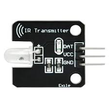
An IR (Infrared) transmitter is a device that emits infrared light signals, which are invisible to the human eye but can be detected by IR receivers. These signals are commonly used for remote control applications, data transmission, and communication between devices. IR transmitters are widely used in consumer electronics, such as televisions, air conditioners, and other home appliances, as well as in robotics and IoT systems.
Explore Projects Built with ir transmitter

Explore Projects Built with ir transmitter
Common Applications and Use Cases
- Remote controls for TVs, air conditioners, and other appliances
- Wireless data transmission between devices
- Communication in robotics and automation systems
- Proximity sensors and object detection
- IoT applications for device control
Technical Specifications
The following table outlines the key technical specifications of the IR transmitter:
| Parameter | Value |
|---|---|
| Manufacturer | IR |
| Manufacturer Part ID | IR |
| Wavelength | 940 nm (typical) |
| Forward Voltage (Vf) | 1.2V to 1.5V |
| Forward Current (If) | 20 mA (typical), 50 mA (max) |
| Beam Angle | 20° to 60° |
| Operating Temperature | -25°C to +85°C |
| Package Type | Through-hole or SMD |
Pin Configuration and Descriptions
The IR transmitter typically has two pins:
| Pin | Name | Description |
|---|---|---|
| 1 | Anode (+) | Connect to the positive terminal of the power supply |
| 2 | Cathode (-) | Connect to the ground or negative terminal |
Usage Instructions
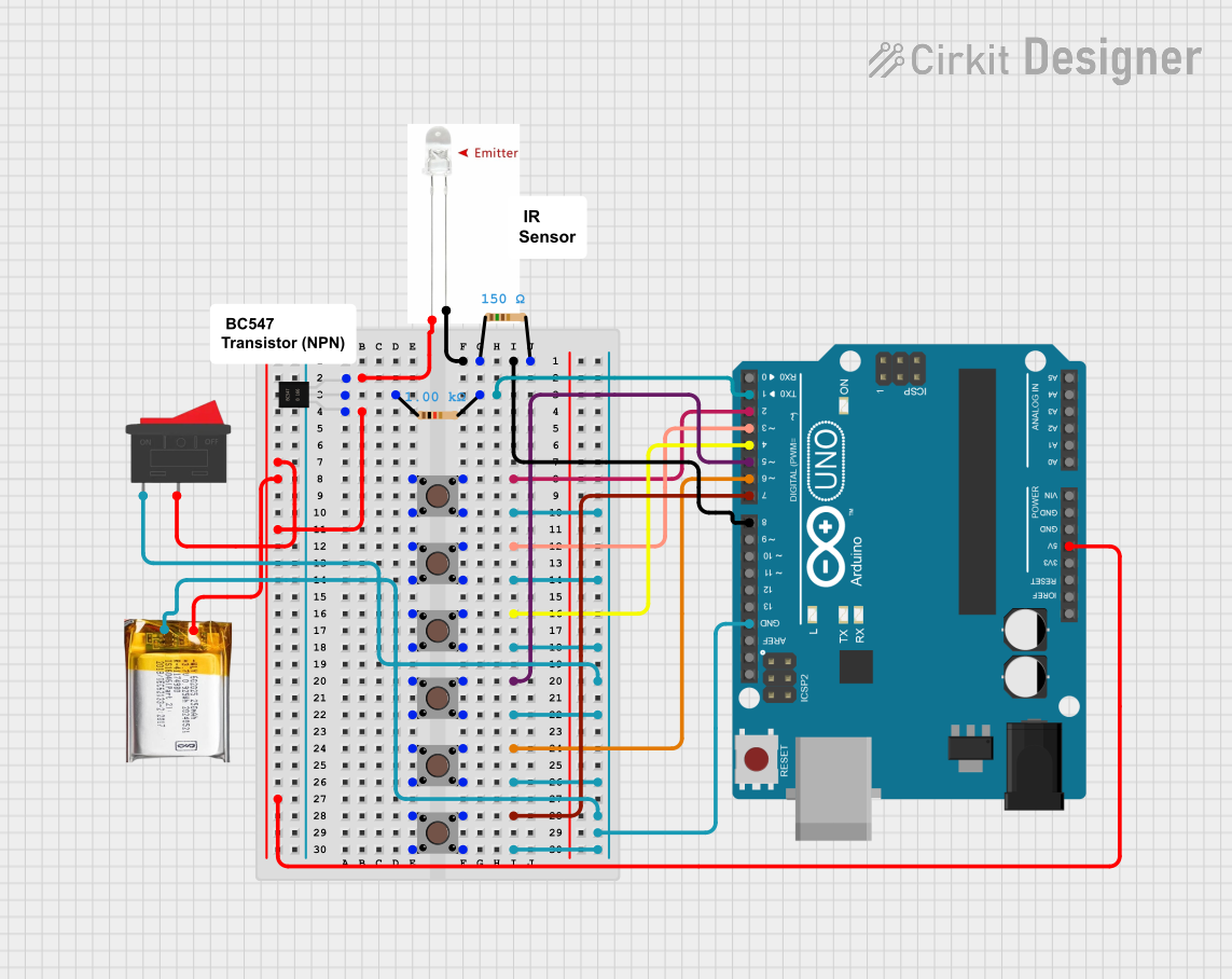
How to Use the IR Transmitter in a Circuit
- Power Supply: Connect the anode pin to a current-limiting resistor (typically 220Ω to 330Ω) and then to the positive terminal of the power supply. Connect the cathode pin to the ground.
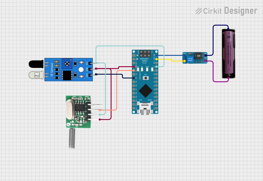
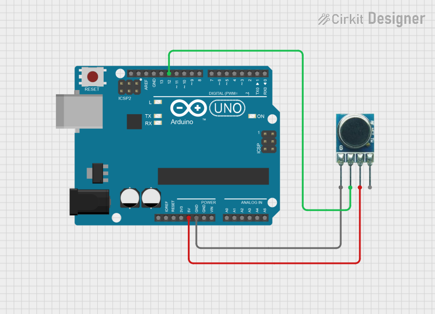
- Signal Input: Use a microcontroller (e.g., Arduino UNO) or other signal source to modulate the current through the IR transmitter. This modulation encodes the data to be transmitted.
- Receiver Pairing: Ensure the IR transmitter is paired with a compatible IR receiver module for proper communication.
Important Considerations and Best Practices
- Current Limiting: Always use a resistor in series with the IR transmitter to prevent excessive current, which can damage the component.
- Line of Sight: Ensure there is a clear line of sight between the IR transmitter and receiver for optimal performance.
- Modulation Frequency: Use a modulation frequency (e.g., 38 kHz) that matches the receiver's specifications.
- Distance: The effective range of the IR transmitter depends on the power of the emitted signal and the sensitivity of the receiver. Typically, it ranges from a few centimeters to several meters.
Example: Using the IR Transmitter with Arduino UNO
Below is an example of how to use the IR transmitter with an Arduino UNO to send a 38 kHz modulated signal:
// Include the IRremote library for IR signal generation
#include <IRremote.h>

// Define the pin connected to the IR transmitter
const int irPin = 3;

void setup() {
  // Initialize the IR transmitter
  IrSender.begin(irPin, ENABLE_LED_FEEDBACK);
  // irPin is the pin connected to the IR transmitter
}

void loop() {
  // Send a 38 kHz modulated signal with a custom data value
  IrSender.sendNEC(0x1FE48B7, 32);
  // 0x1FE48B7 is an example data code, 32 is the number of bits
  delay(2000); // Wait for 2 seconds before sending the next signal
}
Notes:
- Install the
IRremotelibrary in the Arduino IDE before running the code. - Replace
0x1FE48B7with the desired data code for your application.
Troubleshooting and FAQs
Common Issues and Solutions
No Signal Detected by Receiver:
- Ensure the IR transmitter and receiver are aligned properly.
- Verify that the modulation frequency matches the receiver's requirements (e.g., 38 kHz).
- Check the connections and ensure the current-limiting resistor is correctly sized.
Short Transmission Range:
- Increase the current through the IR transmitter by reducing the resistor value (within safe limits).
- Ensure there are no obstructions between the transmitter and receiver.
Overheating:
- Verify that the forward current does not exceed the maximum rating (50 mA).
- Use a resistor to limit the current appropriately.
Interference from Ambient Light:
- Avoid using the IR transmitter in direct sunlight or near strong light sources.
- Use a modulated signal to reduce interference.
FAQs
Q: Can I use the IR transmitter without a microcontroller?
A: Yes, you can use a 555 timer IC or other signal generator to produce a modulated signal for the IR transmitter.
Q: What is the maximum range of the IR transmitter?
A: The range depends on the power of the IR transmitter and the sensitivity of the receiver. Typically, it ranges from 5 to 10 meters indoors.
Q: Can I use the IR transmitter for bidirectional communication?
A: No, the IR transmitter is designed for one-way communication. For bidirectional communication, use an IR transceiver module.
Q: How do I know if the IR transmitter is working?
A: Use a smartphone camera to view the IR transmitter while it is active. The camera can detect the infrared light as a faint purple glow.