How to Use Power Supply Controller: Examples, Pinouts, and Specs
Introduction
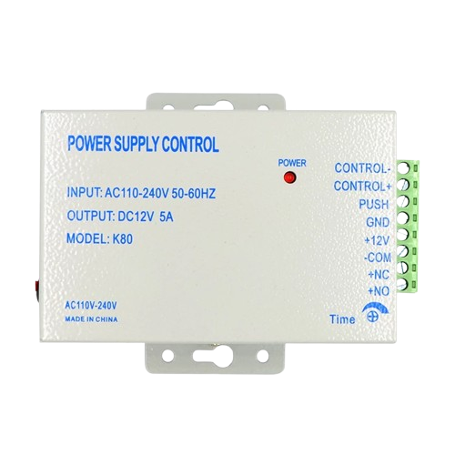
The Power Supply Controller (Part ID: K80) is a versatile electronic component designed to regulate and manage the output voltage and current from a power supply. It ensures stable and efficient power delivery to connected electronic circuits, protecting sensitive components from voltage fluctuations and overcurrent conditions. This device is essential in applications where precise power control is critical, such as in embedded systems, industrial automation, and consumer electronics.
Explore Projects Built with Power Supply Controller


Explore Projects Built with Power Supply Controller
Common Applications
- Voltage regulation in embedded systems
- Power management in industrial equipment
- Battery charging circuits
- Protection of sensitive electronic components
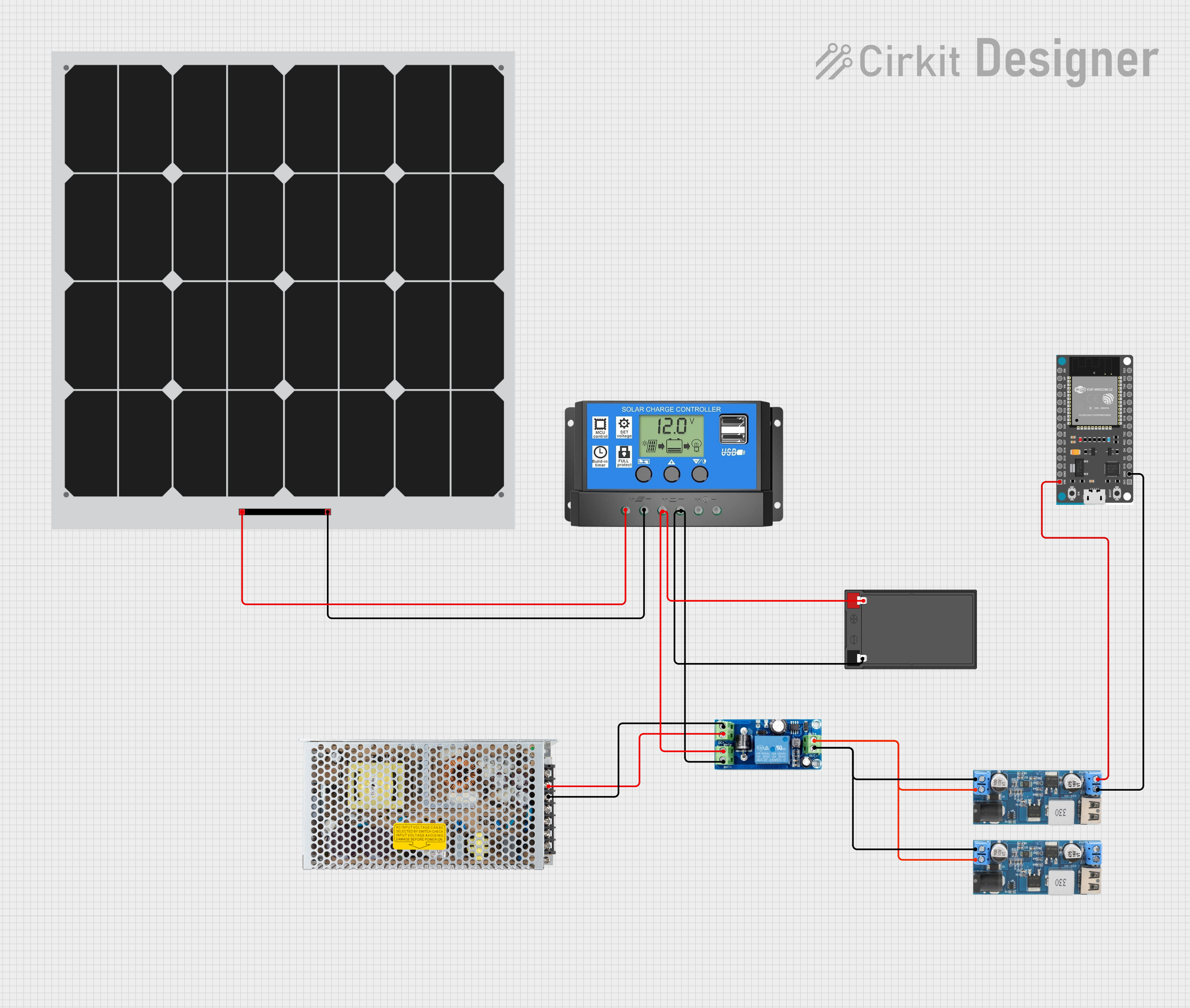
- Renewable energy systems (e.g., solar inverters)
Technical Specifications
Key Technical Details
| Parameter | Value |
|---|---|
| Input Voltage Range | 5V to 40V |
| Output Voltage Range | 1.2V to 36V (adjustable) |
| Maximum Output Current | 3A |
| Efficiency | Up to 95% |
| Operating Temperature | -40°C to +85°C |
| Protection Features | Overvoltage, Overcurrent, |
| Overtemperature, Short Circuit |
Pin Configuration and Descriptions
| Pin Number | Pin Name | Description |
|---|---|---|
| 1 | VIN | Input voltage pin (connect to power source) |
| 2 | GND | Ground pin (common ground for input and output) |
| 3 | VOUT | Regulated output voltage pin |
| 4 | ADJ/FB | Adjustment/feedback pin for setting output voltage |
Usage Instructions
How to Use the Component in a Circuit
Connect the Input Voltage (VIN):
Attach the input voltage source (5V to 40V) to the VIN pin. Ensure the input voltage is within the specified range to avoid damage to the component.Connect the Ground (GND):
Connect the GND pin to the common ground of the circuit.Set the Output Voltage (VOUT):
- Use a resistor divider network connected to the ADJ/FB pin to set the desired output voltage.
- The output voltage can be calculated using the formula:
[ V_{OUT} = V_{REF} \times \left(1 + \frac{R1}{R2}\right) ]
where ( V_{REF} ) is typically 1.25V, and ( R1 ) and ( R2 ) are the resistors in the divider.
Connect the Load:
Attach the load to the VOUT pin. Ensure the load does not exceed the maximum output current of 3A.Optional Capacitors:
- Place a capacitor (e.g., 10µF) between VIN and GND to stabilize the input voltage.
- Place another capacitor (e.g., 22µF) between VOUT and GND to reduce output voltage ripple.
Important Considerations and Best Practices
- Heat Dissipation: If the component operates at high currents, use a heatsink or ensure proper ventilation to prevent overheating.
- Protection: Always use appropriate fuses or circuit breakers to protect the component and the circuit.
- Testing: Verify the output voltage with a multimeter before connecting sensitive devices.
Example: Using the K80 with an Arduino UNO
The K80 can be used to power an Arduino UNO by regulating a higher input voltage (e.g., 12V) down to 5V. Below is an example circuit and Arduino code:
Circuit Setup
- Connect a 12V power source to the VIN pin of the K80.
- Set the output voltage to 5V using a resistor divider.
- Connect the VOUT pin to the Arduino UNO's 5V pin.
- Connect the GND pin to the Arduino's GND.
Arduino Code Example
// Example code to blink an LED using an Arduino UNO powered by the K80
// Ensure the K80 is set to output 5V before connecting to the Arduino

const int ledPin = 13; // Built-in LED pin on Arduino UNO

void setup() {
  pinMode(ledPin, OUTPUT); // Set LED pin as output
}

void loop() {
  digitalWrite(ledPin, HIGH); // Turn the LED on
  delay(1000);               // Wait for 1 second
  digitalWrite(ledPin, LOW);  // Turn the LED off
  delay(1000);               // Wait for 1 second
}
Troubleshooting and FAQs
Common Issues and Solutions
| Issue | Possible Cause | Solution |
|---|---|---|
| No output voltage | Incorrect wiring or no input voltage | Verify connections and input voltage |
| Output voltage too high/low | Incorrect resistor values in divider | Recalculate and adjust resistor values |
| Component overheating | Excessive current or poor ventilation | Add a heatsink or reduce load current |
| Voltage fluctuations | Insufficient input/output capacitors | Add capacitors as recommended |
FAQs
Can the K80 handle AC input?
No, the K80 is designed for DC input only. Use a rectifier circuit to convert AC to DC before connecting to the K80.What happens if the load exceeds 3A?
The K80 includes overcurrent protection and will shut down to prevent damage. Reduce the load to within the specified limit.Can I use the K80 to charge a battery?
Yes, but ensure the output voltage and current are configured according to the battery's specifications.
By following this documentation, users can effectively integrate the K80 Power Supply Controller into their projects for reliable and efficient power management.