
How to Use Atlas Scientific USB Serial Debugger: Examples, Pinouts, and Specs
 Design with Atlas Scientific USB Serial Debugger in Cirkit Designer
Introduction
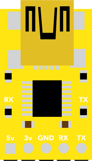
The Atlas Scientific USB Serial Debugger is a versatile device designed to facilitate communication and debugging of Atlas Scientific sensors via a USB interface. It acts as a bridge between your computer and the sensor, enabling seamless data transfer, configuration, and troubleshooting. This tool is particularly useful for developers and engineers working with Atlas Scientific's range of environmental and chemical sensors.
Explore Projects Built with Atlas Scientific USB Serial Debugger
 Open Project in Cirkit Designer
 Open Project in Cirkit Designer
 Open Project in Cirkit Designer
 Open Project in Cirkit Designer
Explore Projects Built with Atlas Scientific USB Serial Debugger
Open Project in Cirkit DesignerOpen Project in Cirkit DesignerOpen Project in Cirkit DesignerOpen Project in Cirkit DesignerCommon Applications and Use Cases
- Debugging and configuring Atlas Scientific sensors.
- Reading real-time data from sensors via a USB connection.
- Testing and troubleshooting sensor functionality.
- Integrating sensors into larger systems for prototyping and development.
Technical Specifications
The Atlas Scientific USB Serial Debugger is designed to work with a wide range of Atlas Scientific sensors. Below are its key technical details:
Key Technical Details
| Parameter | Specification |
|---|---|
| Input Voltage | 5V (via USB) |
| Communication Protocol | UART (Universal Asynchronous Receiver/Transmitter) |
| USB Interface | USB 2.0 Type-A |
| Baud Rate | Configurable (default: 9600 bps) |
| Operating Temperature | 0°C to 50°C |
| Dimensions | 40mm x 20mm x 10mm |
Pin Configuration and Descriptions
The USB Serial Debugger has a simple pinout for connecting to Atlas Scientific sensors. Below is the pin configuration:
| Pin Name | Description |
|---|---|
| TX | Transmit data to the sensor |
| RX | Receive data from the sensor |
| GND | Ground connection |
| VCC | Power supply for the sensor (5V output from USB) |
Usage Instructions
How to Use the Component in a Circuit
Connect the Debugger to the Sensor:
- Connect the
TXpin of the debugger to theRXpin of the sensor. - Connect the
RXpin of the debugger to theTXpin of the sensor. - Connect the
GNDpin of the debugger to theGNDpin of the sensor. - If the sensor requires power, connect the
VCCpin of the debugger to the sensor's power input.
- Connect the
Connect the Debugger to Your Computer:
- Plug the USB Serial Debugger into a USB port on your computer.
Install Necessary Drivers:
- Download and install the appropriate USB-to-serial drivers from the Atlas Scientific website if required.
Open a Serial Terminal:
- Use a serial terminal program (e.g., PuTTY, Tera Term, or Arduino Serial Monitor) to communicate with the sensor.
- Set the baud rate to the sensor's default (typically 9600 bps).
Send Commands to the Sensor:
- Use the serial terminal to send commands to the sensor and receive data. Refer to the sensor's datasheet for a list of supported commands.
Important Considerations and Best Practices
- Ensure that the baud rate of the debugger matches the baud rate of the sensor.
- Avoid connecting the
VCCpin if the sensor is powered by an external source to prevent damage. - Use proper grounding to avoid communication errors.
- Always refer to the specific sensor's documentation for command syntax and configuration details.
Example Code for Arduino UNO
If you are using the USB Serial Debugger with an Arduino UNO, you can use the following example code to communicate with an Atlas Scientific sensor:
#include <SoftwareSerial.h>

// Define the RX and TX pins for the debugger
SoftwareSerial mySerial(10, 11); // RX = pin 10, TX = pin 11

void setup() {
  Serial.begin(9600); // Start the hardware serial monitor
  mySerial.begin(9600); // Start the software serial communication

  Serial.println("Atlas Scientific USB Serial Debugger Example");
  Serial.println("Type a command to send to the sensor:");
}

void loop() {
  // Check if data is available from the serial monitor
  if (Serial.available()) {
    String command = Serial.readStringUntil('\n'); // Read the command
    mySerial.println(command); // Send the command to the sensor
  }

  // Check if data is available from the sensor
  if (mySerial.available()) {
    String response = mySerial.readStringUntil('\n'); // Read the response
    Serial.println("Sensor Response: " + response); // Print the response
  }
}
Troubleshooting and FAQs
Common Issues Users Might Face
No Data Received from the Sensor:
- Cause: Incorrect wiring or baud rate mismatch.
- Solution: Double-check the connections and ensure the baud rate matches the sensor's settings.
USB Debugger Not Recognized by the Computer:
- Cause: Missing or incorrect USB-to-serial drivers.
- Solution: Install the correct drivers from the Atlas Scientific website.
Garbage Data in the Serial Terminal:
- Cause: Incorrect baud rate or loose connections.
- Solution: Verify the baud rate and ensure all connections are secure.
Sensor Not Responding to Commands:
- Cause: Incorrect command syntax or sensor configuration.
- Solution: Refer to the sensor's datasheet for the correct command format.
Solutions and Tips for Troubleshooting
- Use a multimeter to verify the voltage levels on the
VCCandGNDpins. - Test the USB Serial Debugger with a known working sensor to isolate the issue.
- Restart the serial terminal program if communication issues persist.
- Ensure that the USB port on your computer is functioning properly.
By following this documentation, you can effectively use the Atlas Scientific USB Serial Debugger to communicate with and debug Atlas Scientific sensors.