How to Use Módulo QS-1212CCBD 80W buck boost: Examples, Pinouts, and Specs
Introduction
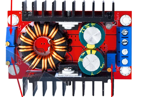
The Módulo QS-1212CCBD 80W is a versatile power module designed for both step-up (boost) and step-down (buck) voltage conversion. This module is ideal for applications requiring stable voltage regulation, making it suitable for a wide range of electronic projects. Whether you need to power a device with a different voltage than your power source or maintain a constant voltage despite fluctuations, the QS-1212CCBD is an excellent choice.
Explore Projects Built with Módulo QS-1212CCBD 80W buck boost


Explore Projects Built with Módulo QS-1212CCBD 80W buck boost
Common Applications and Use Cases
- Battery-Powered Projects: Efficiently manage power from batteries with varying charge levels.
- Solar Power Systems: Regulate voltage from solar panels to charge batteries or power devices.
- Embedded Systems: Provide stable voltage to microcontrollers and sensors.
- Portable Electronics: Power devices with different voltage requirements from a single power source.
- DIY Electronics Projects: Versatile use in various hobbyist and prototyping projects.
Technical Specifications
Key Technical Details
| Parameter | Value |
|---|---|
| Input Voltage Range | 5V - 32V |
| Output Voltage Range | 1V - 30V |
| Maximum Output Power | 80W |
| Efficiency | Up to 95% |
| Switching Frequency | 150kHz |
| Output Ripple | < 50mV |
| Operating Temperature | -40°C to +85°C |
| Dimensions | 60mm x 40mm x 20mm |
Pin Configuration and Descriptions
| Pin No. | Pin Name | Description |
|---|---|---|
| 1 | VIN+ | Positive input voltage |
| 2 | VIN- | Negative input voltage (Ground) |
| 3 | VOUT+ | Positive output voltage |
| 4 | VOUT- | Negative output voltage (Ground) |
| 5 | ADJ | Voltage adjustment (use a potentiometer or fixed resistor) |
Usage Instructions
How to Use the Component in a Circuit
Connect the Input Voltage:
- Connect the positive terminal of your power source to the
VIN+pin. - Connect the negative terminal of your power source to the
VIN-pin.
- Connect the positive terminal of your power source to the
Connect the Output Voltage:
- Connect the positive terminal of your load to the
VOUT+pin. - Connect the negative terminal of your load to the
VOUT-pin.
- Connect the positive terminal of your load to the
Adjust the Output Voltage:
- Use a potentiometer or a fixed resistor connected to the
ADJpin to set the desired output voltage. Turn the potentiometer until the desired voltage is achieved.
- Use a potentiometer or a fixed resistor connected to the
Important Considerations and Best Practices
- Heat Dissipation: Ensure adequate cooling for the module, especially when operating at high power levels. Use heat sinks or active cooling if necessary.
- Input Voltage Range: Do not exceed the specified input voltage range (5V - 32V) to avoid damaging the module.
- Output Voltage Range: Ensure the output voltage is within the specified range (1V - 30V) for stable operation.
- Load Requirements: Verify that the load connected to the module does not exceed the maximum output power of 80W.
- Polarity: Double-check the polarity of the connections to avoid damage to the module and connected devices.
Troubleshooting and FAQs
Common Issues and Solutions
No Output Voltage:
- Check Connections: Ensure all connections are secure and correctly oriented.
- Input Voltage: Verify that the input voltage is within the specified range.
- Adjustment: Ensure the potentiometer or resistor on the
ADJpin is correctly set.
Output Voltage Fluctuations:
- Load Stability: Ensure the load is stable and does not draw more current than the module can supply.
- Input Voltage Stability: Verify that the input voltage is stable and within the specified range.
- Cooling: Ensure adequate cooling to prevent thermal shutdown.
Module Overheating:
- Cooling: Improve cooling with heat sinks or active cooling methods.
- Load: Reduce the load to ensure it does not exceed the module's power rating.
FAQs
Q: Can I use this module with an Arduino UNO? A: Yes, the QS-1212CCBD can be used to power an Arduino UNO by setting the output voltage to 5V. Ensure the input voltage is within the module's specified range.
Q: How do I adjust the output voltage precisely?
A: Use a multimeter to measure the output voltage while adjusting the potentiometer connected to the ADJ pin until the desired voltage is achieved.
Q: What is the efficiency of the module? A: The module has an efficiency of up to 95%, depending on the input and output voltage conditions.
Q: Can I use this module to charge batteries? A: Yes, the module can be used to charge batteries by setting the appropriate output voltage and current limit. Ensure the charging parameters match the battery specifications.
Example Code for Arduino UNO
Here is an example of how to use the QS-1212CCBD module to power an Arduino UNO:
// Example code to demonstrate powering an Arduino UNO using the QS-1212CCBD module

void setup() {
  // Initialize serial communication for debugging
  Serial.begin(9600);
  // Print a message to indicate the setup is complete
  Serial.println("Arduino UNO powered by QS-1212CCBD module");
}

void loop() {
  // Main loop code
  // Add your application code here
  // For demonstration, we'll blink the built-in LED
  digitalWrite(LED_BUILTIN, HIGH); // Turn the LED on
  delay(1000);                     // Wait for 1 second
  digitalWrite(LED_BUILTIN, LOW);  // Turn the LED off
  delay(1000);                     // Wait for 1 second
}
This code initializes the Arduino UNO and blinks the built-in LED to demonstrate that the board is powered correctly by the QS-1212CCBD module. Ensure the module's output voltage is set to 5V before connecting it to the Arduino UNO.