How to Use ST7735 display 128x160: Examples, Pinouts, and Specs
Introduction
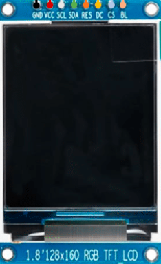
The ST7735 is a compact color display module manufactured by Sitronix Technology Corporation. It features a resolution of 128x160 pixels and is widely used in embedded systems for graphical user interfaces (GUIs) and visual output. This display module is based on the ST7735 driver IC, which provides a simple interface for controlling the display. Its small size, vibrant colors, and low power consumption make it ideal for portable devices, IoT projects, and hobbyist applications.
Explore Projects Built with ST7735 display 128x160


Explore Projects Built with ST7735 display 128x160
Common Applications
- Smartwatches and wearable devices
- Portable gaming consoles
- IoT dashboards and status displays
- Embedded system GUIs
- Educational and hobbyist projects
Technical Specifications
Below are the key technical details of the ST7735 display module:
| Parameter | Value |
|---|---|
| Manufacturer | Sitronix Technology Corporation |
| Part ID | ST7735 |
| Display Resolution | 128x160 pixels |
| Display Type | TFT LCD (Thin-Film Transistor) |
| Color Depth | 18-bit (262,144 colors) |
| Interface | SPI (Serial Peripheral Interface) |
| Operating Voltage | 2.8V to 3.3V |
| Backlight Voltage | 3.0V to 3.3V |
| Operating Temperature | -30°C to 85°C |
| Dimensions | Varies by module (e.g., 1.8-inch) |
Pin Configuration
The ST7735 display module typically uses an SPI interface with the following pin configuration:
| Pin Name | Description |
|---|---|
| VCC | Power supply (2.8V to 3.3V) |
| GND | Ground |
| SCL (CLK) | Serial Clock (SPI clock input) |
| SDA (MOSI) | Serial Data (SPI data input) |
| RES (RST) | Reset pin (active low) |
| DC (A0) | Data/Command control pin |
| CS | Chip Select (active low) |
| BLK | Backlight control (optional, active low) |
Note: Pin names may vary slightly depending on the specific module. Always refer to the datasheet or module documentation for exact details.
Usage Instructions
Connecting the ST7735 to an Arduino UNO
The ST7735 display can be easily interfaced with an Arduino UNO using the SPI protocol. Below is a typical wiring configuration:
| ST7735 Pin | Arduino UNO Pin |
|---|---|
| VCC | 3.3V |
| GND | GND |
| SCL (CLK) | D13 (SCK) |
| SDA (MOSI) | D11 (MOSI) |
| RES (RST) | D8 |
| DC (A0) | D9 |
| CS | D10 |
| BLK | GND (or PWM pin) |
Arduino Code Example
Below is an example Arduino sketch to initialize and display graphics on the ST7735 using the Adafruit ST7735 library:
#include <Adafruit_GFX.h>    // Core graphics library
#include <Adafruit_ST7735.h> // ST7735 driver library
#include <SPI.h>             // SPI library

// Define pins for the ST7735 display
#define TFT_CS   10  // Chip select pin
#define TFT_RST   8  // Reset pin
#define TFT_DC    9  // Data/Command pin

// Initialize the ST7735 display object
Adafruit_ST7735 tft = Adafruit_ST7735(TFT_CS, TFT_DC, TFT_RST);

void setup() {
  // Initialize the display
  tft.initR(INITR_BLACKTAB); // Use INITR_BLACKTAB for most ST7735 modules
  tft.setRotation(1);        // Set display orientation (0-3)

  // Fill the screen with a solid color
  tft.fillScreen(ST77XX_BLACK);

  // Display a message
  tft.setTextColor(ST77XX_WHITE);
  tft.setTextSize(2);
  tft.setCursor(10, 10);
  tft.println("Hello, ST7735!");
}

void loop() {
  // Add your code here to update the display
}
Important Considerations
- Voltage Levels: The ST7735 operates at 3.3V logic levels. If using a 5V microcontroller (e.g., Arduino UNO), use level shifters or voltage dividers to avoid damaging the display.
- Backlight Control: The BLK pin can be connected to GND for constant backlight or to a PWM pin for brightness control.
- Library Compatibility: Ensure you have the latest versions of the Adafruit GFX and Adafruit ST7735 libraries installed in your Arduino IDE.
Troubleshooting and FAQs
Common Issues
Blank Screen:
- Ensure all connections are secure and correct.
- Verify that the display is receiving power (check VCC and GND connections).
- Confirm that the correct initialization code is used (e.g.,
INITR_BLACKTAB).
Distorted or Incorrect Colors:
- Check the SPI connections (SCL, SDA, DC, and CS).
- Ensure the display orientation (
setRotation) matches your project requirements.
No Response from the Display:
- Verify that the reset pin (RES) is properly connected and initialized in the code.
- Ensure the SPI clock speed is not too high for the display module.
FAQs
Q: Can I use the ST7735 with a 5V microcontroller?
A: Yes, but you must use level shifters or voltage dividers to step down the 5V logic signals to 3.3V.
Q: How do I control the backlight brightness?
A: Connect the BLK pin to a PWM-capable pin on your microcontroller and use analogWrite() to adjust brightness.
Q: What is the maximum SPI clock speed for the ST7735?
A: The ST7735 typically supports SPI clock speeds up to 15 MHz. However, check your specific module's datasheet for exact limits.
Q: Can I display images on the ST7735?
A: Yes, you can display BMP images by storing them on an SD card and using the Adafruit GFX library to render them.
By following this documentation, you should be able to successfully integrate and use the ST7735 display module in your projects!