Cirkit Designer Logo
Cirkit Designer
Your all-in-one circuit design IDE
Home / 
Component Documentation

How to Use Micro USB Port: Examples, Pinouts, and Specs

Image of Micro USB Port
Cirkit Designer LogoDesign with Micro USB Port in Cirkit Designer

Introduction

The Micro USB Port is a small, rectangular connector widely used in electronic devices for data transfer and charging purposes. It is a compact and durable interface that has been a standard in mobile phones, tablets, power banks, and other portable devices. Known for its reversible design, the Micro USB Port ensures ease of use and reliable connectivity.

Explore Projects Built with Micro USB Port

Use Cirkit Designer to design, explore, and prototype these projects online. Some projects support real-time simulation. Click "Open Project" to start designing instantly!
USB Type-C Powered LED Circuit with Resistor
Image of Scheme1: A project utilizing Micro USB Port in a practical application
This circuit consists of a USB Type-C port providing power to a red LED through a 1000 Ohm resistor. The resistor limits the current flowing through the LED, which lights up when the circuit is powered.
Cirkit Designer LogoOpen Project in Cirkit Designer
Battery-Powered USB Charger with LED Indicator and DC Motor
Image of Copy of Hand Crank mobile charger : A project utilizing Micro USB Port in a practical application
This circuit converts AC power to DC using a bridge rectifier and regulates the voltage to 5V with a 7805 voltage regulator. It powers a USB port and indicates power status with an LED, while also providing a charging interface through a multi-charging cable.
Cirkit Designer LogoOpen Project in Cirkit Designer
Beelink Mini S12 N95 and Arduino UNO Based Fingerprint Authentication System with ESP32 CAM
Image of design 3: A project utilizing Micro USB Port in a practical application
This circuit features a Beelink MINI S12 N95 computer connected to a 7-inch display via HDMI for video output and two USB connections for power and touch screen functionality. An Arduino UNO is interfaced with a fingerprint scanner for biometric input. The Beelink MINI S12 N95 is powered by a PC power supply, which in turn is connected to a 240V power source. Additionally, an ESP32 CAM module is powered and programmed via a USB plug and an FTDI programmer, respectively, for wireless camera capabilities.
Cirkit Designer LogoOpen Project in Cirkit Designer
ESP32 CAM Wi-Fi Enabled Camera Module with USB Power
Image of abc: A project utilizing Micro USB Port in a practical application
This circuit consists of an ESP32 CAM module powered by a Micro USB breakout board. The USB breakout board supplies 5V and ground to the ESP32 CAM, enabling it to function and perform tasks such as image capture and processing.
Cirkit Designer LogoOpen Project in Cirkit Designer

Explore Projects Built with Micro USB Port

Use Cirkit Designer to design, explore, and prototype these projects online. Some projects support real-time simulation. Click "Open Project" to start designing instantly!
Image of Scheme1: A project utilizing Micro USB Port in a practical application
USB Type-C Powered LED Circuit with Resistor
This circuit consists of a USB Type-C port providing power to a red LED through a 1000 Ohm resistor. The resistor limits the current flowing through the LED, which lights up when the circuit is powered.
Cirkit Designer LogoOpen Project in Cirkit Designer
Image of Copy of Hand Crank mobile charger : A project utilizing Micro USB Port in a practical application
Battery-Powered USB Charger with LED Indicator and DC Motor
This circuit converts AC power to DC using a bridge rectifier and regulates the voltage to 5V with a 7805 voltage regulator. It powers a USB port and indicates power status with an LED, while also providing a charging interface through a multi-charging cable.
Cirkit Designer LogoOpen Project in Cirkit Designer
Image of design 3: A project utilizing Micro USB Port in a practical application
Beelink Mini S12 N95 and Arduino UNO Based Fingerprint Authentication System with ESP32 CAM
This circuit features a Beelink MINI S12 N95 computer connected to a 7-inch display via HDMI for video output and two USB connections for power and touch screen functionality. An Arduino UNO is interfaced with a fingerprint scanner for biometric input. The Beelink MINI S12 N95 is powered by a PC power supply, which in turn is connected to a 240V power source. Additionally, an ESP32 CAM module is powered and programmed via a USB plug and an FTDI programmer, respectively, for wireless camera capabilities.
Cirkit Designer LogoOpen Project in Cirkit Designer
Image of abc: A project utilizing Micro USB Port in a practical application
ESP32 CAM Wi-Fi Enabled Camera Module with USB Power
This circuit consists of an ESP32 CAM module powered by a Micro USB breakout board. The USB breakout board supplies 5V and ground to the ESP32 CAM, enabling it to function and perform tasks such as image capture and processing.
Cirkit Designer LogoOpen Project in Cirkit Designer

Common Applications and Use Cases

  • Charging portable electronic devices such as smartphones, tablets, and cameras.
  • Data transfer between devices and computers.
  • Powering small electronic projects and development boards.
  • Serving as a communication interface for embedded systems.

Technical Specifications

The Micro USB Port is available in two main variants: Micro USB Type-A and Micro USB Type-B. The most commonly used version is Micro USB Type-B. Below are the key technical details:

General Specifications

  • Connector Type: Micro USB Type-B (most common)
  • Voltage Rating: 5V DC (standard USB voltage)
  • Current Rating: Up to 2A (depending on the cable and device)
  • Data Transfer Speed: Up to 480 Mbps (USB 2.0 standard)
  • Durability: Rated for 10,000 insertion/removal cycles
  • Dimensions: Approximately 6.85mm x 1.8mm

Pin Configuration and Descriptions

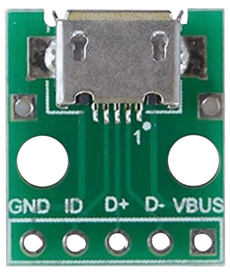
The Micro USB Port typically has 5 pins. Below is the pinout for Micro USB Type-B:

Pin Number Name Description
1 VBUS Power supply (5V DC)
2 D- Data line (negative)
3 D+ Data line (positive)
4 ID Identification pin (used for OTG functionality; connected to GND in standard)
5 GND Ground

Usage Instructions

How to Use the Micro USB Port in a Circuit

  1. Power Supply: Connect the VBUS pin to a 5V power source and the GND pin to the ground of your circuit. Ensure the power source can supply sufficient current for your application.
  2. Data Communication: Use the D+ and D- pins for data transfer. These pins should be connected to the corresponding data lines of the device or microcontroller.
  3. OTG Functionality: For On-The-Go (OTG) applications, the ID pin can be used to determine the device's role (host or peripheral). Connect the ID pin to GND for standard device operation.

Important Considerations and Best Practices

  • Voltage Regulation: Ensure the connected device can handle the 5V supply. Use a voltage regulator if necessary.
  • Cable Quality: Use high-quality Micro USB cables to avoid voltage drops and ensure reliable data transfer.
  • Insertion Orientation: Although the Micro USB Port is not fully reversible like USB-C, its design minimizes incorrect insertion. Always align the connector properly to avoid damage.
  • Soldering: When soldering a Micro USB Port onto a PCB, ensure proper alignment and avoid overheating the pins.

Example: Connecting a Micro USB Port to an Arduino UNO

The Arduino UNO does not natively use a Micro USB Port, but you can use a Micro USB breakout board to power the Arduino or communicate with it. Below is an example of powering an Arduino UNO using a Micro USB breakout board:

// Example: Powering Arduino UNO with a Micro USB breakout board
// Connect the breakout board's VBUS pin to the Arduino's 5V pin
// Connect the breakout board's GND pin to the Arduino's GND pin

void setup() {
  // No specific setup required for power-only connections
}

void loop() {
  // Your Arduino code goes here
}

Troubleshooting and FAQs

Common Issues and Solutions

  1. Device Not Charging or Powering On

    • Cause: Insufficient current from the power source.
    • Solution: Use a power source capable of supplying at least 1A or more, depending on the device's requirements.
  2. Data Transfer Fails

    • Cause: Faulty or low-quality cable.
    • Solution: Replace the cable with a high-quality Micro USB cable.
  3. Connector Feels Loose

    • Cause: Worn-out port or connector.
    • Solution: Replace the Micro USB Port or cable.
  4. Overheating

    • Cause: Excessive current draw or poor soldering.
    • Solution: Check the circuit for short circuits or excessive load. Ensure proper soldering of the port.

FAQs

  • Q: Can I use a Micro USB Port for 3.3V devices?
    A: Yes, but you must use a voltage regulator to step down the 5V supply to 3.3V.

  • Q: Is the Micro USB Port compatible with USB-C?
    A: No, but adapters are available to connect Micro USB devices to USB-C ports.

  • Q: How do I identify the pins on a Micro USB Port?
    A: Refer to the pinout table above. Use a multimeter to verify connections if needed.

This concludes the documentation for the Micro USB Port.