Cirkit Designer Logo
Cirkit Designer
Your all-in-one circuit design IDE
Home / 
Component Documentation

How to Use IBT-2 H-Bridge Motor Driver: Examples, Pinouts, and Specs

Image of IBT-2 H-Bridge Motor Driver
Cirkit Designer LogoDesign with IBT-2 H-Bridge Motor Driver in Cirkit Designer

Introduction

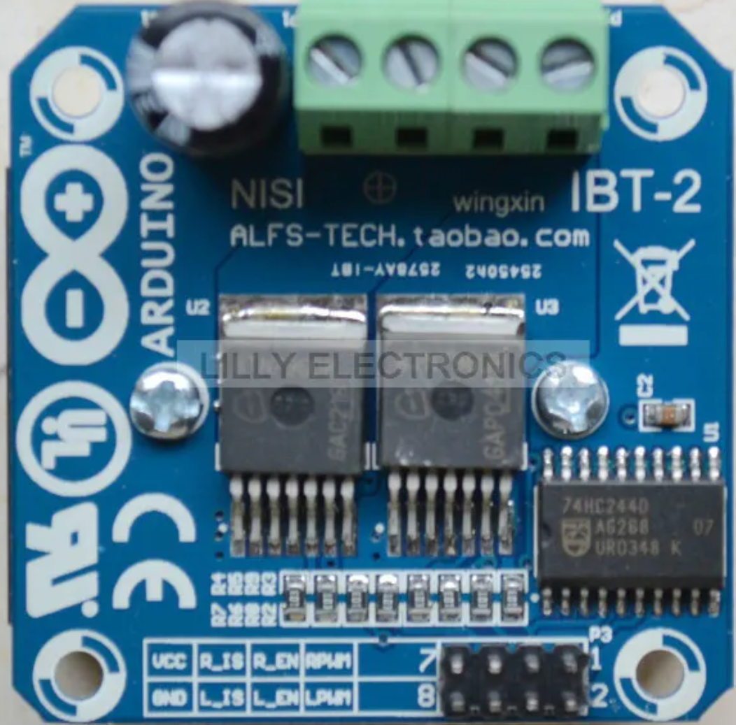
The IBT-2 H-Bridge Motor Driver is a robust electronic component designed for controlling DC motors' direction and speed. It is capable of driving high-power motors in both forward and reverse directions. This makes it an ideal choice for robotics, automation projects, and any application requiring bidirectional motor control.

Explore Projects Built with IBT-2 H-Bridge Motor Driver

Use Cirkit Designer to design, explore, and prototype these projects online. Some projects support real-time simulation. Click "Open Project" to start designing instantly!
ESP32-Controlled Multi-Axis Actuator System with Orientation Sensing and Light Detection
Image of Auto_Level_Table: A project utilizing IBT-2 H-Bridge Motor Driver in a practical application
This circuit features an ESP32 S3 N32R8V microcontroller interfaced with multiple IBT-2 H-Bridge Motor Drivers to control several Linear Actuators, and it receives input from KY-018 LDR Photo Resistors and Pushbuttons. The ESP32 is powered by a 5V supply from an Adafruit MPM3610 5V Buck Converter, while the Linear Actuators and Motor Drivers are powered by a 12V 7Ah battery. Additionally, the ESP32 communicates with an Adafruit BNO085 9-DOF Orientation IMU Fusion Breakout for orientation sensing.
Cirkit Designer LogoOpen Project in Cirkit Designer
Arduino Mega 2560 Controlled Multi-Motor Robot with RC Receiver and H-Bridge Drivers
Image of battle bot: A project utilizing IBT-2 H-Bridge Motor Driver in a practical application
This circuit is designed to control multiple DC motors using an Arduino Mega 2560 microcontroller and IBT-2 H-Bridge Motor Drivers. The Arduino receives input signals from an RC receiver and drives the motors at variable speeds, including forward and backward directions, as well as stopping them. The system is powered by a 12V battery, and the microcontroller's code provides functions for motor speed calibration, reading transmitter signals, and testing individual motor movements.
Cirkit Designer LogoOpen Project in Cirkit Designer
Arduino-Controlled Line Following Robot with H-Bridge Motor Driver and IR Sensors
Image of seguidor de linea: A project utilizing IBT-2 H-Bridge Motor Driver in a practical application
This circuit is designed to control two DC motors using an H-bridge (ponte h) connected to an Arduino UNO microcontroller. The Arduino receives input from two TCRT 5000 IR sensors to determine the path and controls the motors to move forward, backward, or turn left/right based on the sensor readings. The motors are powered by a 2x 18650 battery pack, and the entire system is intended for applications such as line following robots or automated guided vehicles.
Cirkit Designer LogoOpen Project in Cirkit Designer
Arduino Leonardo-Based Motion Detection and Distance Measurement System
Image of Circuit diagram for Automatic Sliding Door: A project utilizing IBT-2 H-Bridge Motor Driver in a practical application
This circuit features an Arduino Leonardo microcontroller interfaced with multiple sensors and a motor driver. Four limit switches are connected to digital inputs for position sensing, two PIR motion sensors are connected for motion detection, and an HC-SR04 ultrasonic sensor is used for distance measurement. An IBT-2 H-Bridge motor driver is controlled by the Arduino to drive a DC motor, with power supplied by a DC power source.
Cirkit Designer LogoOpen Project in Cirkit Designer

Explore Projects Built with IBT-2 H-Bridge Motor Driver

Use Cirkit Designer to design, explore, and prototype these projects online. Some projects support real-time simulation. Click "Open Project" to start designing instantly!
Image of Auto_Level_Table: A project utilizing IBT-2 H-Bridge Motor Driver in a practical application
ESP32-Controlled Multi-Axis Actuator System with Orientation Sensing and Light Detection
This circuit features an ESP32 S3 N32R8V microcontroller interfaced with multiple IBT-2 H-Bridge Motor Drivers to control several Linear Actuators, and it receives input from KY-018 LDR Photo Resistors and Pushbuttons. The ESP32 is powered by a 5V supply from an Adafruit MPM3610 5V Buck Converter, while the Linear Actuators and Motor Drivers are powered by a 12V 7Ah battery. Additionally, the ESP32 communicates with an Adafruit BNO085 9-DOF Orientation IMU Fusion Breakout for orientation sensing.
Cirkit Designer LogoOpen Project in Cirkit Designer
Image of battle bot: A project utilizing IBT-2 H-Bridge Motor Driver in a practical application
Arduino Mega 2560 Controlled Multi-Motor Robot with RC Receiver and H-Bridge Drivers
This circuit is designed to control multiple DC motors using an Arduino Mega 2560 microcontroller and IBT-2 H-Bridge Motor Drivers. The Arduino receives input signals from an RC receiver and drives the motors at variable speeds, including forward and backward directions, as well as stopping them. The system is powered by a 12V battery, and the microcontroller's code provides functions for motor speed calibration, reading transmitter signals, and testing individual motor movements.
Cirkit Designer LogoOpen Project in Cirkit Designer
Image of seguidor de linea: A project utilizing IBT-2 H-Bridge Motor Driver in a practical application
Arduino-Controlled Line Following Robot with H-Bridge Motor Driver and IR Sensors
This circuit is designed to control two DC motors using an H-bridge (ponte h) connected to an Arduino UNO microcontroller. The Arduino receives input from two TCRT 5000 IR sensors to determine the path and controls the motors to move forward, backward, or turn left/right based on the sensor readings. The motors are powered by a 2x 18650 battery pack, and the entire system is intended for applications such as line following robots or automated guided vehicles.
Cirkit Designer LogoOpen Project in Cirkit Designer
Image of Circuit diagram for Automatic Sliding Door: A project utilizing IBT-2 H-Bridge Motor Driver in a practical application
Arduino Leonardo-Based Motion Detection and Distance Measurement System
This circuit features an Arduino Leonardo microcontroller interfaced with multiple sensors and a motor driver. Four limit switches are connected to digital inputs for position sensing, two PIR motion sensors are connected for motion detection, and an HC-SR04 ultrasonic sensor is used for distance measurement. An IBT-2 H-Bridge motor driver is controlled by the Arduino to drive a DC motor, with power supplied by a DC power source.
Cirkit Designer LogoOpen Project in Cirkit Designer

Common Applications and Use Cases

  • Robotics
  • Automated machinery
  • Electric vehicles
  • Conveyor systems
  • Actuators for mechanical systems

Technical Specifications

Key Technical Details

  • Supply Voltage (Vcc): 6V to 27V
  • Logic Voltage (Vlogic): 5V (compatible with Arduino)
  • Continuous Current: Up to 43A
  • Peak Current: 100A (for a few seconds)
  • Operating Temperature: -25°C to +135°C

Pin Configuration and Descriptions

Pin Number Pin Name Description
1 RPWM Right PWM input for motor speed and direction
2 LPWM Left PWM input for motor speed and direction
3 R_EN Right Enable input
4 L_EN Left Enable input
5 Vcc Power supply for motor (6V to 27V)
6 GND Ground
7 B+ Motor power supply positive
8 B- Motor power supply negative

Usage Instructions

How to Use the Component in a Circuit

  1. Power Connections:

    • Connect the motor's positive lead to the B+ pin and the negative lead to the B- pin.
    • Apply a DC voltage between 6V and 27V to the Vcc pin for the motor power supply.
    • Connect the ground of the power supply to the GND pin.
  2. Control Connections:

    • Connect the R_EN and L_EN pins to a digital output on your control board (e.g., Arduino) to enable or disable the motor driver.
    • Apply PWM signals to the RPWM and LPWM pins to control the motor's speed and direction.

Important Considerations and Best Practices

  • Ensure that the power supply can handle the motor's current requirements.
  • Use a flyback diode across the motor terminals to protect the driver from voltage spikes.
  • Avoid running the motor driver at its peak current for extended periods to prevent overheating.
  • Implement proper heat dissipation techniques if operating near the maximum current rating.

Example Code for Arduino UNO

// Define the control pins for the IBT-2
const int RPWM = 3; // Right PWM pin connected to Arduino pin 3
const int LPWM = 5; // Left PWM pin connected to Arduino pin 5
const int R_EN = 4; // Right Enable pin connected to Arduino pin 4
const int L_EN = 6; // Left Enable pin connected to Arduino pin 6

void setup() {
  // Set all the control pins as outputs
  pinMode(RPWM, OUTPUT);
  pinMode(LPWM, OUTPUT);
  pinMode(R_EN, OUTPUT);
  pinMode(L_EN, OUTPUT);

  // Enable the motor driver
  digitalWrite(R_EN, HIGH);
  digitalWrite(L_EN, HIGH);
}

void loop() {
  // Spin motor forward at full speed
  analogWrite(RPWM, 255); // Full speed forward
  analogWrite(LPWM, 0);   // Ensure LPWM is low
  delay(2000);             // Run for 2 seconds

  // Spin motor in reverse at half speed
  analogWrite(RPWM, 0);    // Ensure RPWM is low
  analogWrite(LPWM, 127);  // Half speed reverse
  delay(2000);             // Run for 2 seconds

  // Stop the motor
  analogWrite(RPWM, 0);
  analogWrite(LPWM, 0);
  delay(2000);             // Stop for 2 seconds
}

Troubleshooting and FAQs

Common Issues

  • Motor not responding: Check power supply connections and ensure that the enable pins are set high.
  • Overheating: Ensure proper heat dissipation and that the current does not exceed the continuous rating.
  • Erratic motor behavior: Verify that the PWM signals are correctly applied and that there is no interference.

Solutions and Tips for Troubleshooting

  • Double-check wiring and solder joints for any loose connections or shorts.
  • Use a multimeter to verify the voltage at the motor driver's power pins.
  • Implement a gradual start/stop in your code to reduce mechanical stress and electrical spikes.

FAQs

Q: Can I control two motors with one IBT-2? A: No, the IBT-2 is designed to control one motor. For two motors, you would need two IBT-2 modules.

Q: What is the maximum PWM frequency for the IBT-2? A: The IBT-2 can handle PWM frequencies up to 25kHz.

Q: How do I reverse the motor direction? A: To reverse the motor direction, invert the PWM signals: apply the PWM signal to LPWM for forward and RPWM for reverse.

Q: Can I use the IBT-2 with a microcontroller running at 3.3V logic? A: While the IBT-2 is designed for 5V logic, it may work at 3.3V. However, it is recommended to use a logic level converter for reliable operation.