How to Use Relay 4 Channel 3.3v: Examples, Pinouts, and Specs
Introduction
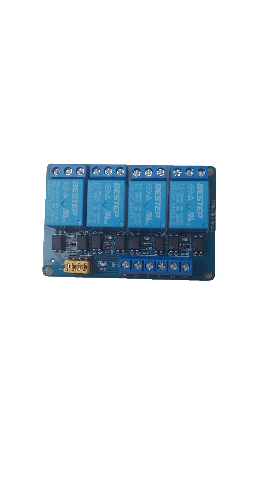
The Relay 4 Channel 3.3V module is a versatile electronic component designed to control up to four independent devices using a low voltage signal, typically 3.3V, from a microcontroller or other control systems. This module is ideal for applications requiring electrical isolation and the ability to switch higher voltage loads, such as home automation, industrial control systems, and robotics.
Common applications include:
- Controlling high-power devices like lights, fans, and motors.
- Home automation systems for switching appliances.
- Industrial equipment control.
- Robotics projects requiring isolated control of external devices.
Explore Projects Built with Relay 4 Channel 3.3v


Explore Projects Built with Relay 4 Channel 3.3v
Technical Specifications
The Relay 4 Channel 3.3V module is designed to interface seamlessly with microcontrollers like Arduino, Raspberry Pi, and ESP32. Below are its key technical details:
General Specifications
- Operating Voltage: 3.3V DC
- Trigger Voltage: 3.3V DC (low-level trigger)
- Relay Type: Electromechanical
- Number of Channels: 4
- Maximum Load (per channel):
- AC: 250V at 10A
- DC: 30V at 10A
- Isolation: Optocoupler-based electrical isolation
- Dimensions: ~75mm x 55mm x 20mm
- Weight: ~60g
Pin Configuration and Descriptions
The module has two main interfaces: the control pins and the relay output terminals.
Control Pins
| Pin Name | Description |
|---|---|
| VCC | Power supply input (3.3V DC) |
| GND | Ground connection |
| IN1 | Control signal for Relay 1 (active low) |
| IN2 | Control signal for Relay 2 (active low) |
| IN3 | Control signal for Relay 3 (active low) |
| IN4 | Control signal for Relay 4 (active low) |
Relay Output Terminals
Each relay channel has three output terminals:
| Terminal | Description |
|---|---|
| NO (Normally Open) | Open circuit when the relay is inactive. Closes when activated. |
| COM (Common) | Common terminal for the relay. |
| NC (Normally Closed) | Closed circuit when the relay is inactive. Opens when activated. |
Usage Instructions
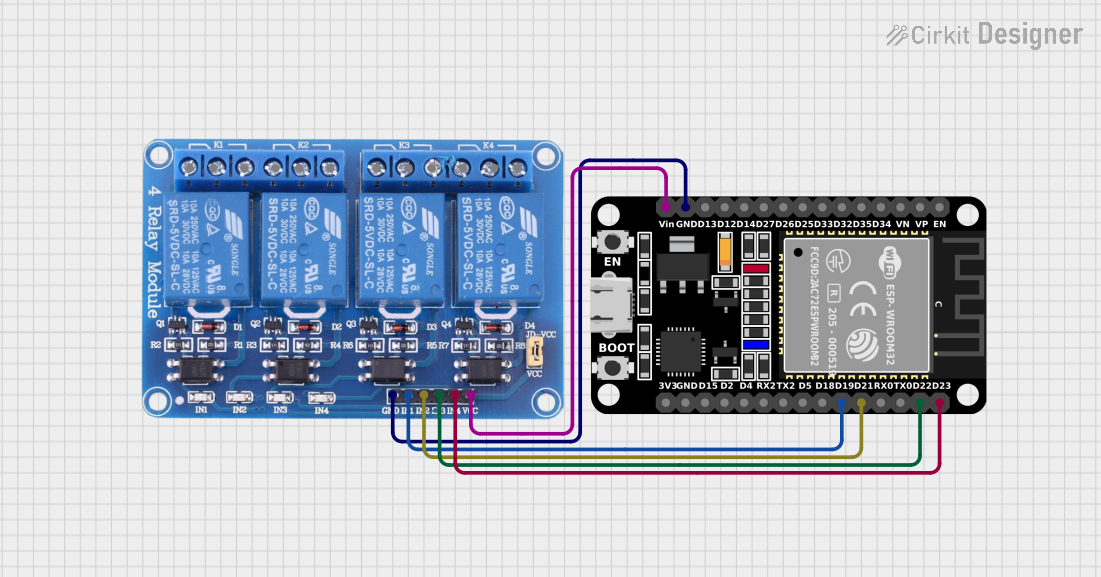
How to Use the Relay 4 Channel 3.3V Module in a Circuit
Power the Module:
- Connect the VCC pin to a 3.3V power source and the GND pin to ground.
- Ensure the power supply can provide sufficient current for all active relays (approximately 70mA per relay).
Connect the Control Signals:
- Connect the IN1, IN2, IN3, and IN4 pins to the digital output pins of your microcontroller.
- When the control pin is set to LOW, the corresponding relay will activate.
Connect the Load:
- For each relay, connect the device you want to control to the NO, NC, and COM terminals as required.
- Example: For a light bulb, connect one wire to the COM terminal and the other to the NO terminal.
Write the Control Code:
- Use your microcontroller to send LOW signals to the control pins to activate the relays.
Important Considerations and Best Practices
- Electrical Isolation: The module uses optocouplers for isolation, but ensure proper grounding to avoid noise or interference.
- Load Ratings: Do not exceed the maximum voltage and current ratings of the relays.
- Inductive Loads: For inductive loads like motors, use a flyback diode across the load to prevent voltage spikes.
- Power Supply: Ensure the power supply is stable and can handle the current requirements of all active relays.
Example Code for Arduino UNO
Below is an example code to control the Relay 4 Channel 3.3V module using an Arduino UNO:
// Define the relay control pins
#define RELAY1 2  // Relay 1 connected to digital pin 2
#define RELAY2 3  // Relay 2 connected to digital pin 3
#define RELAY3 4  // Relay 3 connected to digital pin 4
#define RELAY4 5  // Relay 4 connected to digital pin 5

void setup() {
  // Set relay pins as outputs
  pinMode(RELAY1, OUTPUT);
  pinMode(RELAY2, OUTPUT);
  pinMode(RELAY3, OUTPUT);
  pinMode(RELAY4, OUTPUT);

  // Initialize all relays to OFF (HIGH state)
  digitalWrite(RELAY1, HIGH);
  digitalWrite(RELAY2, HIGH);
  digitalWrite(RELAY3, HIGH);
  digitalWrite(RELAY4, HIGH);
}

void loop() {
  // Example: Turn on Relay 1 for 2 seconds, then turn it off
  digitalWrite(RELAY1, LOW);  // Activate Relay 1
  delay(2000);                // Wait for 2 seconds
  digitalWrite(RELAY1, HIGH); // Deactivate Relay 1
  delay(1000);                // Wait for 1 second

  // Repeat similar actions for other relays as needed
}
Troubleshooting and FAQs
Common Issues and Solutions
Relays Not Activating:
- Cause: Insufficient power supply or incorrect wiring.
- Solution: Verify the power supply voltage and current. Check all connections.
Microcontroller Resetting When Relays Activate:
- Cause: Voltage spikes or insufficient power supply.
- Solution: Use a separate power supply for the relay module or add a capacitor to stabilize the power.
Load Not Switching:
- Cause: Incorrect wiring of the load to the relay terminals.
- Solution: Double-check the connections to the NO, NC, and COM terminals.
Relays Stuck in ON or OFF State:
- Cause: Damaged relay or incorrect control signal.
- Solution: Test the relay with a direct control signal. Replace if necessary.
FAQs
Q: Can I use this module with a 5V microcontroller?
A: Yes, but you will need to use a level shifter or resistor divider to step down the control signals to 3.3V.
Q: Is it safe to control AC appliances with this module?
A: Yes, as long as the load does not exceed the relay's maximum ratings (250V AC, 10A).
Q: Can I control all four relays simultaneously?
A: Yes, but ensure your power supply can handle the total current draw (~280mA for all relays).
Q: Do I need external components to use this module?
A: No, the module is self-contained, but you may need a flyback diode for inductive loads.