
How to Use DIP Switch 3 Position: Examples, Pinouts, and Specs
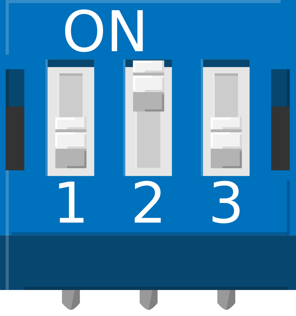
 Design with DIP Switch 3 Position in Cirkit Designer
Introduction
A DIP (Dual In-line Package) Switch with 3 positions is a compact, mechanical switch module used to control the flow of electricity within a circuit. Each switch in the package can be independently toggled between an ON or OFF state, allowing for a combination of settings that can be used to configure the operation of electronic devices. Common applications include setting hardware preferences, configuring device addresses, and selecting modes of operation in electronic circuits.
Explore Projects Built with DIP Switch 3 Position
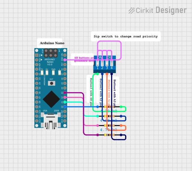
 Open Project in Cirkit Designer
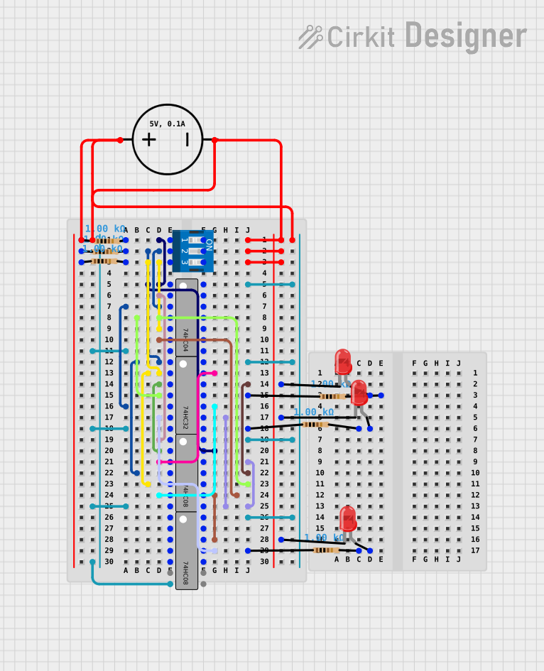
 Open Project in Cirkit Designer
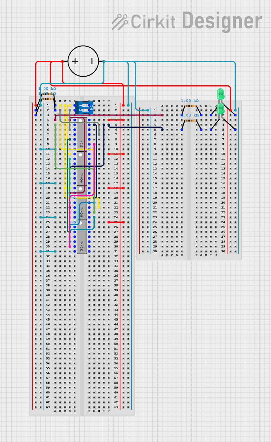
 Open Project in Cirkit Designer
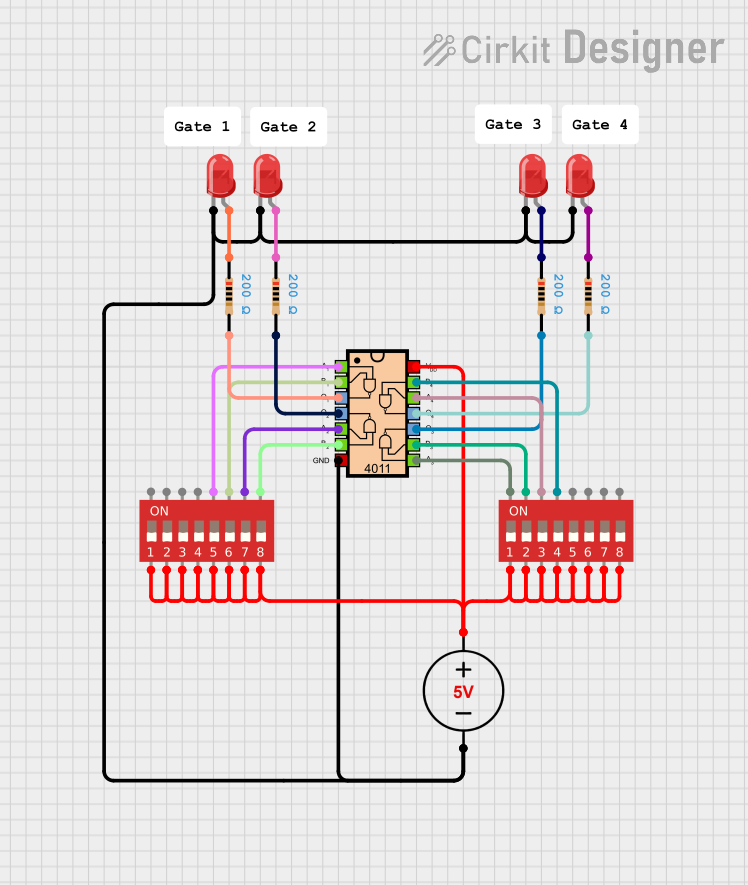
 Open Project in Cirkit Designer
Explore Projects Built with DIP Switch 3 Position

 Open Project in Cirkit Designer
 Open Project in Cirkit Designer
 Open Project in Cirkit Designer
 Open Project in Cirkit Designer
Technical Specifications
General Features
- Switch Type: Slide (Standard)
- Number of Positions: 3
- Contact Rating: 25mA @ 24VDC
- Insulation Resistance: 100M Ohms min. at 500VDC
- Dielectric Strength: 500VAC for 1 minute
- Operating Temperature Range: -20°C to +70°C
- Mechanical Life: 1000 cycles per switch
Pin Configuration and Descriptions
| Pin Number | Description | State |
|---|---|---|
| 1 | Switch 1 (S1) | ON/OFF |
| 2 | Common Pin (C1) | - |
| 3 | Switch 2 (S2) | ON/OFF |
| 4 | Common Pin (C2) | - |
| 5 | Switch 3 (S3) | ON/OFF |
| 6 | Common Pin (C3) | - |
Each switch (S1, S2, S3) has an associated common pin (C1, C2, C3) that is connected internally to the switch. The common pins are the points where the circuit's input or output is connected, and the switch pins are toggled to make or break the connection.
Usage Instructions
Integration into a Circuit
- Power Off: Ensure that the power supply to the circuit is turned off before integrating the DIP switch.
- Mounting: Place the DIP switch onto the circuit board with the correct orientation, ensuring that the pins align with the designated holes or solder pads.
- Soldering: Solder the pins to the board, taking care not to overheat the switch or the surrounding components.
- Configuration: Set the switches to the desired ON or OFF positions according to the circuit requirements.
Best Practices
- Avoid excessive force when toggling the switches to prevent mechanical damage.
- Use a small tool like a screwdriver or a pen tip for precise control when changing switch positions.
- Ensure that the DIP switch is mounted away from high-heat components to prevent warping or damage.
- Verify the switch positions before powering up the circuit to avoid incorrect configurations.
Troubleshooting and FAQs
Q: What if the DIP switch does not seem to change the circuit behavior? A: Check the solder joints for cold solder or bridges. Ensure that the switch is in the correct position and that the circuit is powered.
Q: How can I clean the DIP switch if it becomes dirty or oxidized? A: Use a contact cleaner spray designed for electronic components. Apply the spray and toggle the switches several times to clean the contacts.
Q: The DIP switch feels loose or does not stay in position; what can I do? A: The switch may be damaged or worn out. Consider replacing the DIP switch if it does not maintain its position.
Q: Can I use the DIP switch with higher voltages or currents? A: Exceeding the specified voltage or current ratings can damage the switch and the circuit. Stick to the recommended specifications.
Example Code for Arduino UNO
The following example demonstrates how to read the state of a 3-position DIP switch connected to an Arduino UNO.
// Define the pins connected to the DIP switch
const int switchPins[] = {2, 3, 4}; // DIP switch pins connected to digital pins 2, 3, and 4

void setup() {
  Serial.begin(9600);
  // Set the switch pins as inputs with pull-up resistors
  for (int i = 0; i < 3; i++) {
    pinMode(switchPins[i], INPUT_PULLUP);
  }
}

void loop() {
  // Read the state of each switch and print it to the serial monitor
  for (int i = 0; i < 3; i++) {
    int switchState = digitalRead(switchPins[i]);
    Serial.print("Switch ");
    Serial.print(i + 1);
    Serial.print(": ");
    Serial.println(switchState == HIGH ? "OFF" : "ON");
  }
  delay(1000); // Wait for a second before reading again
}
This code initializes the Arduino's digital pins 2, 3, and 4 as inputs with internal pull-up resistors. It then reads the state of each switch every second and prints whether the switch is in the ON or OFF position to the serial monitor. Remember that when using pull-up resistors, the logic will be inverted; a HIGH reading means the switch is OFF, and a LOW reading means the switch is ON.