Cirkit Designer Logo
Cirkit Designer
Your all-in-one circuit design IDE
Home / 
Component Documentation

How to Use EWRF TS5832: Examples, Pinouts, and Specs

Image of EWRF TS5832
Cirkit Designer LogoDesign with EWRF TS5832 in Cirkit Designer

Introduction

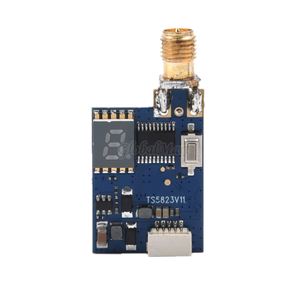
The EWRF TS5832 is a 5.8GHz 32-channel video transmitter designed for FPV (First Person View) systems. It is commonly used in drones and RC vehicles to provide reliable video transmission over long distances. This component is essential for enthusiasts and professionals who require high-quality video feeds for navigation, surveillance, or entertainment purposes.

Explore Projects Built with EWRF TS5832

Use Cirkit Designer to design, explore, and prototype these projects online. Some projects support real-time simulation. Click "Open Project" to start designing instantly!
Satellite-Based Timing and Navigation System with SDR and Atomic Clock Synchronization
Image of GPS 시스템 측정 구성도_Confirm: A project utilizing EWRF TS5832 in a practical application
This circuit appears to be a complex system involving power supply management, GPS and timing synchronization, and data communication. It includes a SI-TEX G1 Satellite Compass for GPS data, an XHTF1021 Atomic Rubidium Clock for precise timing, and Ettus USRP B200 units for software-defined radio communication. Power is supplied through various SMPS units and distributed via terminal blocks and DC jacks. Data communication is facilitated by Beelink MINI S12 N95 computers, RS232 splitters, and a 1000BASE-T Media Converter for network connectivity. RF Directional Couplers are used to interface antennas with the USRP units, and the entire system is likely contained within cases for protection and organization.
Cirkit Designer LogoOpen Project in Cirkit Designer
Battery-Powered nRF52840 and HT-RA62 Communication Module
Image of NRF52840+HT-RA62: A project utilizing EWRF TS5832 in a practical application
This circuit is a wireless communication system powered by a 18650 Li-ion battery, featuring an nRF52840 ProMicro microcontroller and an HT-RA62 transceiver module. The nRF52840 handles the control logic and interfaces with the HT-RA62 for data transmission, while the battery provides the necessary power for the entire setup.
Cirkit Designer LogoOpen Project in Cirkit Designer
ESP32-Based RF Communication System with 433 MHz Modules
Image of 433 mhz: A project utilizing EWRF TS5832 in a practical application
This circuit comprises an ESP32 microcontroller connected to a 433 MHz RF transmitter and receiver pair. The ESP32 is programmed to receive and decode RF signals through the receiver module, as well as send RF signals via the transmitter module. Additionally, the ESP32 can communicate with a Bluetooth device to exchange commands and data, and it uses an LED for status indication.
Cirkit Designer LogoOpen Project in Cirkit Designer
Satellite Compass and Network-Integrated GPS Data Processing System
Image of GPS 시스템 측정 구성도_241016: A project utilizing EWRF TS5832 in a practical application
This circuit comprises a satellite compass, a mini PC, two GPS antennas, power supplies, a network switch, media converters, and an atomic rubidium clock. The satellite compass is powered by a triple output DC power supply and interfaces with an RS232 splitter for 1PPS signals. The mini PCs are connected to the USRP B200 devices via USB for data and power, and to media converters via Ethernet, which in turn connect to a network switch using fiber optic links. The antennas are connected to the USRP B200s through RF directional couplers, and the atomic clock provides a 1PPS input to the RS232 splitter.
Cirkit Designer LogoOpen Project in Cirkit Designer

Explore Projects Built with EWRF TS5832

Use Cirkit Designer to design, explore, and prototype these projects online. Some projects support real-time simulation. Click "Open Project" to start designing instantly!
Image of GPS 시스템 측정 구성도_Confirm: A project utilizing EWRF TS5832 in a practical application
Satellite-Based Timing and Navigation System with SDR and Atomic Clock Synchronization
This circuit appears to be a complex system involving power supply management, GPS and timing synchronization, and data communication. It includes a SI-TEX G1 Satellite Compass for GPS data, an XHTF1021 Atomic Rubidium Clock for precise timing, and Ettus USRP B200 units for software-defined radio communication. Power is supplied through various SMPS units and distributed via terminal blocks and DC jacks. Data communication is facilitated by Beelink MINI S12 N95 computers, RS232 splitters, and a 1000BASE-T Media Converter for network connectivity. RF Directional Couplers are used to interface antennas with the USRP units, and the entire system is likely contained within cases for protection and organization.
Cirkit Designer LogoOpen Project in Cirkit Designer
Image of NRF52840+HT-RA62: A project utilizing EWRF TS5832 in a practical application
Battery-Powered nRF52840 and HT-RA62 Communication Module
This circuit is a wireless communication system powered by a 18650 Li-ion battery, featuring an nRF52840 ProMicro microcontroller and an HT-RA62 transceiver module. The nRF52840 handles the control logic and interfaces with the HT-RA62 for data transmission, while the battery provides the necessary power for the entire setup.
Cirkit Designer LogoOpen Project in Cirkit Designer
Image of 433 mhz: A project utilizing EWRF TS5832 in a practical application
ESP32-Based RF Communication System with 433 MHz Modules
This circuit comprises an ESP32 microcontroller connected to a 433 MHz RF transmitter and receiver pair. The ESP32 is programmed to receive and decode RF signals through the receiver module, as well as send RF signals via the transmitter module. Additionally, the ESP32 can communicate with a Bluetooth device to exchange commands and data, and it uses an LED for status indication.
Cirkit Designer LogoOpen Project in Cirkit Designer
Image of GPS 시스템 측정 구성도_241016: A project utilizing EWRF TS5832 in a practical application
Satellite Compass and Network-Integrated GPS Data Processing System
This circuit comprises a satellite compass, a mini PC, two GPS antennas, power supplies, a network switch, media converters, and an atomic rubidium clock. The satellite compass is powered by a triple output DC power supply and interfaces with an RS232 splitter for 1PPS signals. The mini PCs are connected to the USRP B200 devices via USB for data and power, and to media converters via Ethernet, which in turn connect to a network switch using fiber optic links. The antennas are connected to the USRP B200s through RF directional couplers, and the atomic clock provides a 1PPS input to the RS232 splitter.
Cirkit Designer LogoOpen Project in Cirkit Designer

Technical Specifications

Key Technical Details

Parameter Value
Frequency Range 5.8GHz
Channels 32
Output Power 200mW
Input Voltage 7V - 24V
Current Consumption 200mA @ 12V
Video Format NTSC/PAL
Antenna Connector SMA
Dimensions 36mm x 22mm x 8mm
Weight 8g

Pin Configuration and Descriptions

Pin Number Pin Name Description
1 GND Ground
2 VCC Power Supply (7V - 24V)
3 VIDEO IN Video Input
4 AUDIO IN Audio Input
5 CH+ Channel Selection Button
6 LED Channel Indicator LED

Usage Instructions

How to Use the EWRF TS5832 in a Circuit

  1. Power Supply: Connect the VCC pin to a power source within the range of 7V to 24V. Ensure that the power supply can provide at least 200mA of current.
  2. Ground Connection: Connect the GND pin to the ground of your circuit.
  3. Video Input: Connect the VIDEO IN pin to the video output of your camera or video source.
  4. Audio Input: If audio transmission is required, connect the AUDIO IN pin to the audio output of your source.
  5. Channel Selection: Use the CH+ button to cycle through the 32 available channels. The current channel will be indicated by the LED.
  6. Antenna: Attach an appropriate 5.8GHz antenna to the SMA connector to ensure optimal transmission range and quality.

Important Considerations and Best Practices

  • Heat Dissipation: The EWRF TS5832 can generate heat during operation. Ensure proper ventilation or use a heat sink to prevent overheating.
  • Antenna Matching: Use a high-quality, matched antenna to avoid damage to the transmitter and to ensure the best performance.
  • Power Supply: Use a stable and clean power supply to avoid noise and interference in the video signal.
  • Legal Compliance: Ensure that the use of the 5.8GHz frequency band complies with local regulations and laws.

Troubleshooting and FAQs

Common Issues and Solutions

  1. No Video Signal:

    • Check Connections: Ensure that all connections are secure and correct.
    • Power Supply: Verify that the power supply is within the specified range and providing sufficient current.
    • Channel Matching: Ensure that the receiver is set to the same channel as the transmitter.
  2. Poor Video Quality:

    • Antenna: Check the antenna connection and ensure it is properly matched.
    • Interference: Avoid operating near other devices that use the 5.8GHz frequency band.
    • Power Supply Noise: Use a clean power supply to minimize noise.
  3. Overheating:

    • Ventilation: Ensure proper ventilation or use a heat sink.
    • Power Supply: Avoid using a power supply that exceeds the recommended voltage range.

FAQs

Q: Can I use the EWRF TS5832 with an Arduino UNO? A: Yes, you can use the EWRF TS5832 with an Arduino UNO to control the channel selection. Below is an example code to cycle through channels using a button connected to the Arduino.

// Arduino UNO code to cycle through channels on EWRF TS5832
const int buttonPin = 2; // Pin connected to CH+ button
const int ledPin = 13;   // Onboard LED for indication

int buttonState = 0;     // Variable for reading the button status

void setup() {
  pinMode(buttonPin, INPUT);
  pinMode(ledPin, OUTPUT);
  digitalWrite(ledPin, LOW);
}

void loop() {
  buttonState = digitalRead(buttonPin);

  if (buttonState == HIGH) {
    digitalWrite(ledPin, HIGH); // Turn on LED when button is pressed
    delay(100);                 // Debounce delay
    digitalWrite(ledPin, LOW);  // Turn off LED
    delay(100);                 // Debounce delay
  }
}

This code reads the state of a button connected to pin 2 and toggles the onboard LED on the Arduino UNO. You can modify this code to control the CH+ pin on the EWRF TS5832.

Conclusion

The EWRF TS5832 is a versatile and reliable video transmitter for FPV systems. By following the usage instructions and best practices outlined in this documentation, you can ensure optimal performance and longevity of the component. If you encounter any issues, refer to the troubleshooting section for solutions.